鈥?/div>
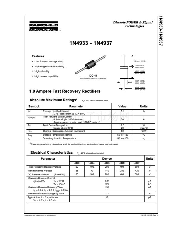
Low forward voltage drop.
High surge current capability.
High reliability.
High current capability.
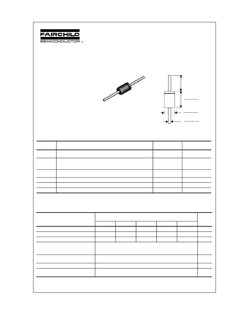
1.0 min (25.4)
Dimensions in
inches (mm)
0.205 (5.21)
0.160 (4.06)
DO-41
COLOR BAND DENOTES CATHODE
0.107 (2.72)
0.080 (2.03)
0.034 (0.86)
0.028 (0.71)
1.0 Ampere Fast Recovery Rectifiers
Absolute Maximum Ratings*
Symbol
I
O
i
f(surge)
T
A
= 25掳C unless otherwise noted
Parameter
Average Rectified Current
.375 " lead length @ T
A
= 50掳C
Peak Forward Surge Current
8.3 ms single half-sine-wave
Superimposed on rated load (JEDEC method)
Total Device Dissipation
Derate above 25掳C
Thermal Resistance, Junction to Ambient
Storage Temperature Range
Operating Junction Temperature
Value
1.0
Units
A
30
2.5
20
50
-50 to +150
-50 to +150
A
W
mW /掳C
掳C/W
掳C
掳C
P
D
R
胃JA
T
stg
T
J
*
These ratings are limiting values above which the serviceability of any semiconductor device may be impaired.
Electrical Characteristics
Parameter
T
A
= 25掳C unless otherwise noted
Device
4933
4934
100
70
100
4935
200
140
200
5.0
100
150
1.2
12
4936
400
280
400
4937
600
420
600
50
35
50
Units
V
V
V
碌A
碌A
nS
V
pF
Peak Repetitive Reverse Voltage
Maximum RMS Voltage
DC Reverse Voltage
(Rated V
R
)
Maximum Reverse Current
@ rated V
R
T
A
= 25掳C
T
A
= 100掳C
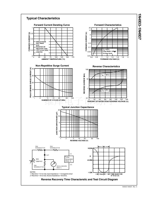
Maximum Reverse Recovery Time
I
F
= 0.5 A, I
R
= 1.0 A, I
RR
= 0.25 A
Maximum Forward Voltage @ 1.0 A
Typical Junction Capacitance
V
R
= 4.0 V, f = 1.0 MHz
漏1999
Fairchild Semiconductor Corporation
1N4933-1N4937, Rev. A


 1
1
 2
2
 3
3
