鈥?/div>
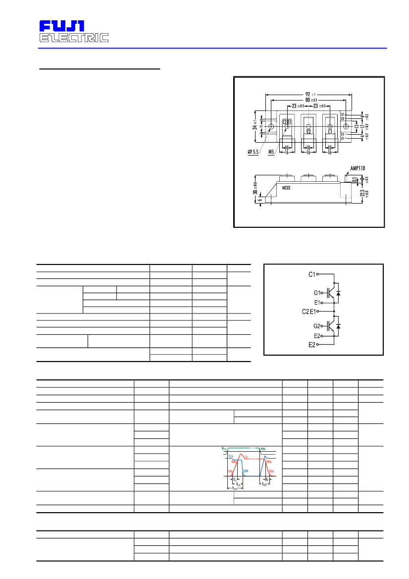
Electrical Characteristics
Items
Zero Gate Voltage Collector Current
Gate-Emitter Leackage Current
Gate-Emitter Threshold Voltage
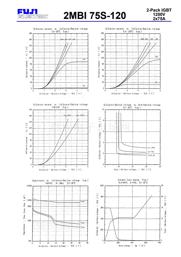
Collector-Emitter Saturation Voltage
Input Capacitance
Output Capacitance
Reverse Transfer Capacitance
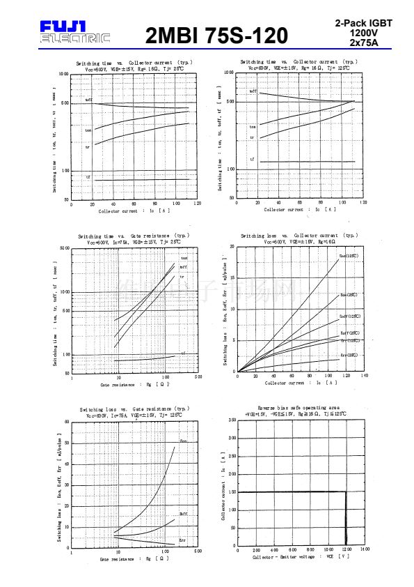
Turn-on Time
I
CES
I
GES
V
GE(th)
V
CE(sat)
C
ies
C
oes
C
res
t
ON
t
r,x
t
r,i
t
OFF
t
f
V
F
t
rr
Turn-off Time
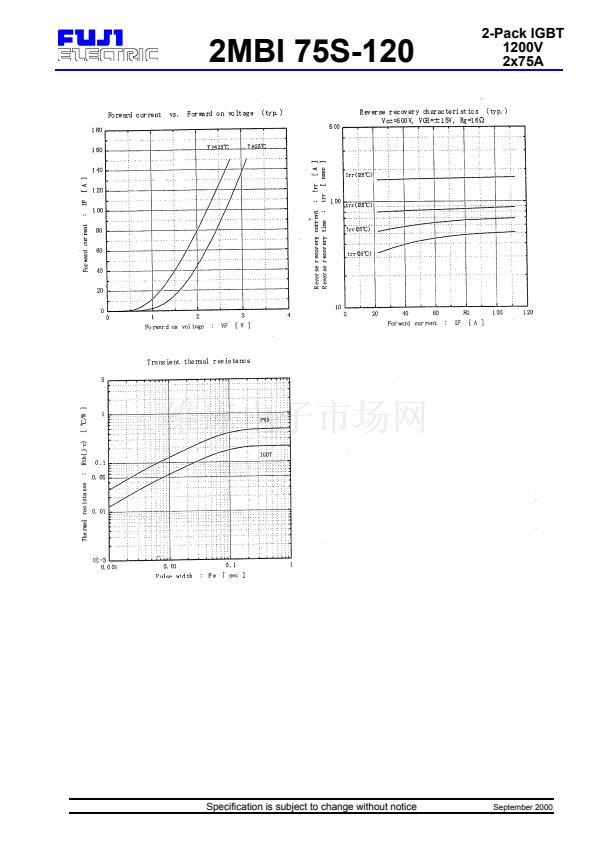
Diode Forward On-Voltage
Reverse Recovery Time
Test Conditions
V
GE
=0V V
CE
=1200V
V
CE
=0V V
GE
=卤 20V
V
GE
=20V I
C
=75mA
T
j
= 25掳C
V
GE
=15V I
C
=75A
T
j
=125掳C
V
GE
=0V
V
CE
=10V
f=1MHz
V
CC
= 600V
I
C
= 75A
V
GE
=
卤15V
R
G
= 16鈩?/div>
Inductive Load
I
F
=75A; V
GE
=0V
I
F
=75A
T
j
= 25掳C
T
j
=125掳C
Min.
Typ.
5.5
7.2
2.3
2.8
9鈥?00
1鈥?75
1鈥?50
0.35
0.25
0.10
0.45
0.08
2.3
2.0
Max.
1.0
200
8.5
2.6
Units
mA
nA
V
pF
1.2
0.6
1.0
0.3
3.0
350
碌s
V
ns
鈥?/div>
Thermal Characteristics
Items
Thermal Resistance
Symbols
Test Conditions
IGBT
Diode
With Thermal Compound
Min.
Typ.
R
th(j-c)
R
th(j-c)
R
th(c-f)
Max.
0.21
0.47
Units
掳C/W
0.05


 1
1
 2
2
 3
3
 4
4
