庐
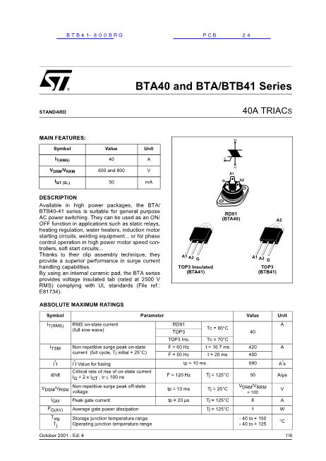
BTA40 and BTA/BTB41 Series
40A TRIAC
S
STANDARD
MAIN FEATURES:
Symbol
I
T(RMS)
V
DRM
/V
RRM
I
GT (Q
1
)
Value
40
600 and 800
50
Unit
A
V
mA
G
G
A2
A1
A1
A2
DESCRIPTION
Available in high power packages, the BTA/
BTB40-41 series is suitable for general purpose
AC power switching. They can be used as an ON/
OFF function in applications such as static relays,
heating regulation, water heaters, induction motor
starting circuits, welding equipment... or for phase
control operation in high power motor speed con-
trollers, soft start circuits...
Thanks to their clip assembly technique, they
provide a superior performance in surge current
handling capabilities.
By using an internal ceramic pad, the BTA series
provides voltage insulated tab (rated at 2500 V
RMS) complying with UL standards (File ref.:
E81734).
ABSOLUTE MAXIMUM RATINGS
Symbol
I
T(RMS)
RMS on-state current
(full sine wave)
Parameter
RD91
(BTA40)
A2
A1 A2
G
A1 A2
G
TOP3 Insulated
(BTA41)
TOP3
(BTB41)
Value
RD91
TOP3
TOP3 Ins.
F = 60 Hz
F = 50 Hz
tp = 10 ms
F = 120 Hz
tp = 10 ms
tp = 20
碌s
Tj = 125掳C
Tj = 25掳C
Tj = 125掳C
Tj = 125掳C
Tc = 80掳C
Tc = 70掳C
t = 16.7 ms
t = 20 ms
420
400
880
50
V
DRM
/V
RRM
+ 100
Unit
A
40
A
I
TSM
It
dI/dt
Non repetitive surge peak on-state
current (full cycle, Tj initial = 25掳C)
I t Value for fusing
Critical rate of rise of on-state current
I
G
= 2 x I
GT
, tr
鈮?/div>
100 ns
As
A/碌s
V
A
W
掳C
1/6
V
DSM
/V
RSM
Non repetitive surge peak off-state
voltage
I
GM
P
G(AV)
T
stg
T
j
Peak gate current
Average gate power dissipation
Storage junction temperature range
Operating junction temperature range
8
1
- 40 to + 150
- 40 to + 125
October 2001 - Ed: 4


 1
1
 2
2
 3
3
 4
4
 5
5
 6
6
