Hall Device
LT120A
LT120A
s
Features
隆
Small temperature coefficient of the Hall voltage
隆
Good linearity of the Hall voltage
隆
Small imbalanced voltage
隆
Directly DC voltage applicable
s
Applications
隆
Brushless motors
VCR, CD, CD-ROM, FDD
隆
Measuring equipment
Gauss meters, magnetic substance detectors
隆
Noncontact sensors
Microswitches, tape-end detection
隆
Other magnetic detection
s
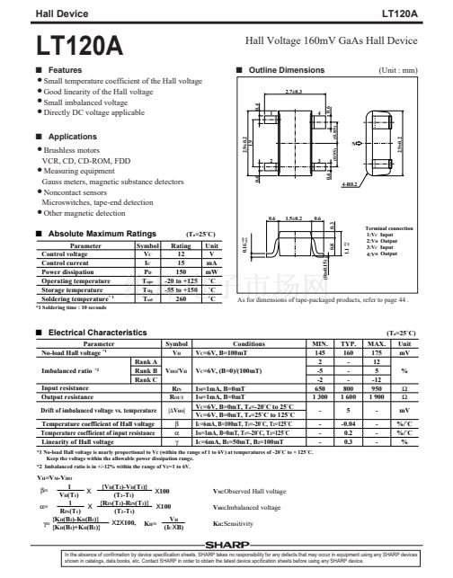
Absolute Maximum Ratings
Parameter
Control voltage
Control current
Power dissipation
Operating temperature
Storage temperature
Soldering temperature
* 1
*1 Soldering time : 10 seconds
Hall Voltage 160mV GaAs Hall Device
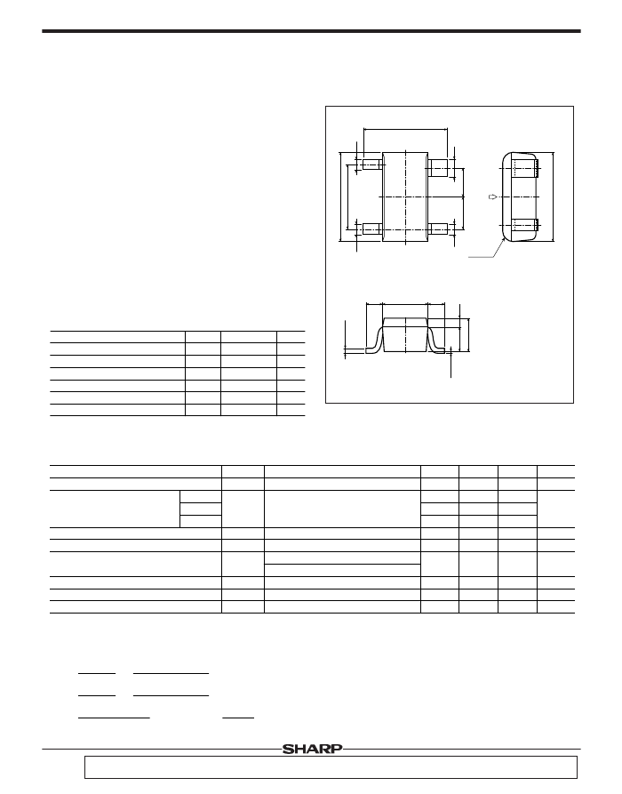
s
Outline Dimensions
2.7卤0.3
0.4
0.6
(Unit : mm)
1
4
2.9卤0.2
1.9
(0.85)
N
2
0.4
3
0.4
(0.95)
4-R0.2
0.6
1.5卤0.2
0.6
0.3
0.16
+0.10
-0.06
(T
a
=25藲C)
Unit
V
mA
mW
藲C
藲C
藲C
Symbol
Rating
V
C
12
I
C
15
P
D
150
T
opr
-20 to +125
T
stg
-55 to +150
T
sol
260
Terminal connection
1:V
C
Input
2:V
H
Output
3:V
C
Input
4:V
H
Output
As for dimensions of tape-packaged products, refer to page 44 .
s
Electrical Characteristics
Parameter
No-load Hall voltage
*1
Imbalanced ratio
Input resistance
Output resistance
Drift of imbalanced voltage vs. temperature
Temperature coefficient of Hall voltage
Temperature coefficient of input resistance
Linearity of Hall voltage
*2
(0to0.15)
1.1
+0.2
-0.1
0.8
(T
a
=25藲C)
Symbol
V
H
Conditions
V
C
=6V, B=100mT
V
C
=6V, (B=0)/(100mT)
I
M
=1mA, B=0mT
I
M
=1mA, B=0mT
V
C
=6V, B=0mT, T
a
=-20藲C to 25藲C
V
C
=6V, B=0mT, T
a
=25藲C to 125藲C
I
C
=6mA, B=100mT, T
1
=-20藲C, T
2
=125藲C
I
M
=1mA, B=0mT, T
1
=-20藲C, T
2
=125藲C
I
C
=6mA, B
1
=50mT, B
2
=100mT
MIN.
145
2
-5
-2
650
1 300
-
-
-
-
TYP.
160
-
-
-
800
1 600
5
-0.04
0.2
0.3
MAX.
175
12
5
-12
950
1 900
-
-
-
-
Unit
mV
%
鈩?/div>
鈩?/div>
mV
%/藲C
%/藲C
%
Rank A
Rank B
Rank C
V
HO
/V
H
R
IN
R
OUT
|鈭哣
HO
|
尾
伪
纬
*1 No-load Hall voltage is nearly proportional to Vc (within the range of 1 to 6V) at temperatures of -20藲C to + 125藲C.
Keep the voltage within the allowable power dissipation range.
*2 Imbalanced ratio is in +/-12% within the range of Vc=1 to 6V.
V
H
=V
M
-V
HO
1
{V
H
(T
2
)-V
H
(T
1
)}
尾=
X100
X
V
H
(T
1
)
(T
2
-T
1
)
{R
IN
(T
2
)-R
IN
(T
1
)}
1
X
X100
伪=
(T
2
-T
1
)
R
IN
(T
1
)
{K
H
(B
2
)-K
H
(B
1
)}
V
H
X2X100,
K
H
=
纬=
(I
C
XB)
{K
H
(B
1
)+K
H
(B
2
)}
V
M
:Observed
Hall voltage
V
HO
:Imbalanced
voltage
K
H
:Sensitivity
In the absence of confirmation by device specification sheets, SHARP takes no responsibility for any defects that may occur in equipment using any SHARP devices
shown in catalogs, data books, etc. Contact SHARP in order to obtain the latest device spcification sheets before using any SHARP device.
2.9卤0.2


 1
1
 2
2
