19-2706; Rev 0; 11/02
MAX9993 Evaluation Kit
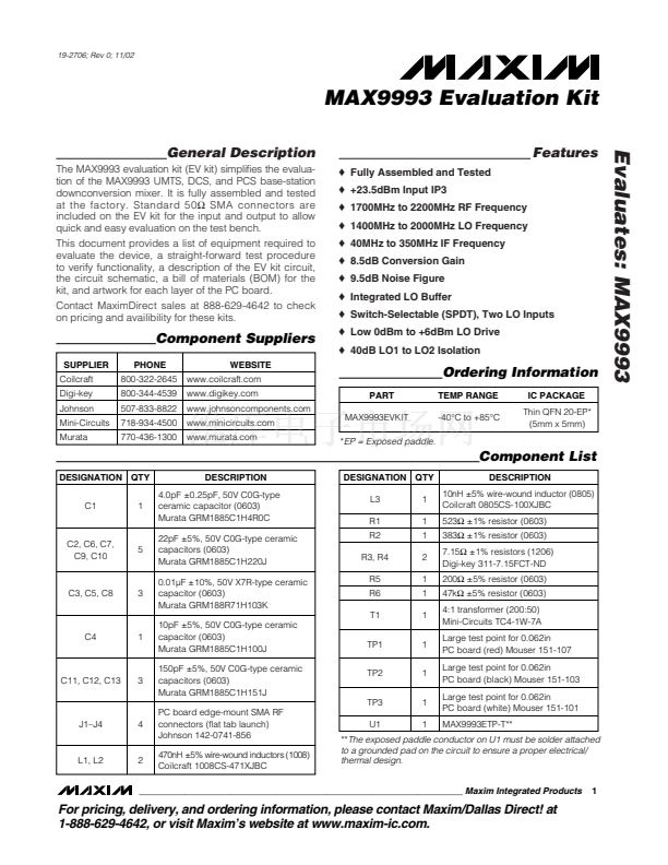
General Description
The MAX9993 evaluation kit (EV kit) simplifies the evalua-
tion of the MAX9993 UMTS, DCS, and PCS base-station
downconversion mixer. It is fully assembled and tested
at the factory. Standard 50鈩?SMA connectors are
included on the EV kit for the input and output to allow
quick and easy evaluation on the test bench.
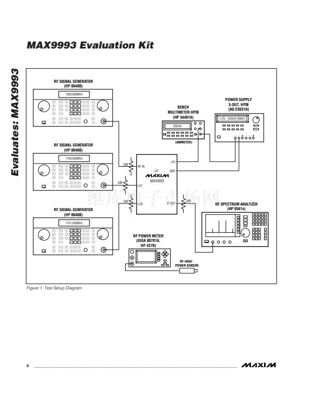
This document provides a list of equipment required to
evaluate the device, a straight-forward test procedure
to verify functionality, a description of the EV kit circuit,
the circuit schematic, a bill of materials (BOM) for the
kit, and artwork for each layer of the PC board.
Contact MaximDirect sales at 888-629-4642 to check
on pricing and availibility for these kits.
o
Fully Assembled and Tested
o
+23.5dBm Input IP3
o
1700MHz to 2200MHz RF Frequency
o
1400MHz to 2000MHz LO Frequency
o
40MHz to 350MHz IF Frequency
o
8.5dB Conversion Gain
o
9.5dB Noise Figure
o
Integrated LO Buffer
o
Switch-Selectable (SPDT), Two LO Inputs
o
Low 0dBm to +6dBm LO Drive
o
40dB LO1 to LO2 Isolation
Features
Evaluates: MAX9993
Component Suppliers
SUPPLIER
Coilcraft
Digi-key
Johnson
Mini-Circuits
Murata
PHONE
800-322-2645
800-344-4539
507-833-8822
718-934-4500
770-436-1300
WEBSITE
www.coilcraft.com
www.digikey.com
www.johnsoncomponents.com
www.minicircuits.com
www.murata.com
Ordering Information
PART
MAX9993EVKIT
TEMP RANGE
-40掳C to +85掳C
IC PACKAGE
Thin QFN 20-EP*
(5mm x 5mm)
*EP
= Exposed paddle.
Component List
DESIGNATION QTY
C1
1
DESCRIPTION
4.0pF 卤0.25pF, 50V C0G-type
ceramic capacitor (0603)
Murata GRM1885C1H4R0C
22pF 卤5%, 50V C0G-type ceramic
capacitors (0603)
Murata GRM1885C1H220J
0.01碌F 卤10%, 50V X7R-type ceramic
capacitor (0603)
Murata GRM188R71H103K
10pF 卤5%, 50V C0G-type ceramic
capacitor (0603)
Murata GRM1885C1H100J
150pF 卤5%, 50V C0G-type ceramic
capacitors (0603)
Murata GRM1885C1H151J
PC board edge-mount SMA RF
connectors (flat tab launch)
Johnson 142-0741-856
470nH 卤5% wire-wound inductors (1008)
Coilcraft 1008CS-471XJBC
DESIGNATION QTY
L3
R1
R2
R3, R4
R5
R6
T1
C4
1
TP1
TP2
TP3
J1鈥揓4
4
U1
1
1
1
2
1
1
1
1
1
1
1
DESCRIPTION
10nH 卤5% wire-wound inductor (0805)
Coilcraft 0805CS-100XJBC
523鈩?卤1% resistor (0603)
383鈩?卤1% resistor (0603)
7.15鈩?卤1% resistors (1206)
Digi-key 311-7.15FCT-ND
200鈩?卤5% resistor (0603)
47k鈩?卤5% resistor (0603)
4:1 transformer (200:50)
Mini-Circuits TC4-1W-7A
Large test point for 0.062in
PC board (red) Mouser 151-107
Large test point for 0.062in
PC board (black) Mouser 151-103
Large test point for 0.062in
PC board (white) Mouser 151-101
MAX9993ETP-T**
C2, C6, C7,
C9, C10
5
C3, C5, C8
3
C11, C12, C13
3
L1, L2
2
**The
exposed paddle conductor on U1 must be solder attached
to a grounded pad on the circuit to ensure a proper electrical/
thermal design.
1
________________________________________________________________
Maxim Integrated Products
For pricing, delivery, and ordering information, please contact Maxim/Dallas Direct! at
1-888-629-4642, or visit Maxim鈥檚 website at www.maxim-ic.com.


 1
1
 2
2
 3
3
 4
4
 5
5
 6
6
 7
7
