M
鈥?PIC16CR54C
Device
Pins
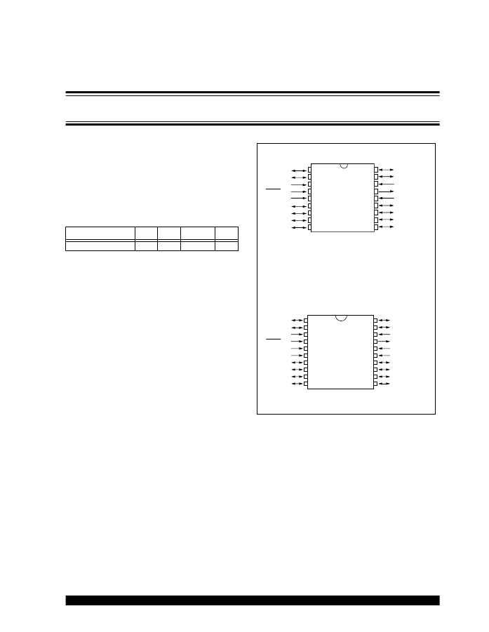
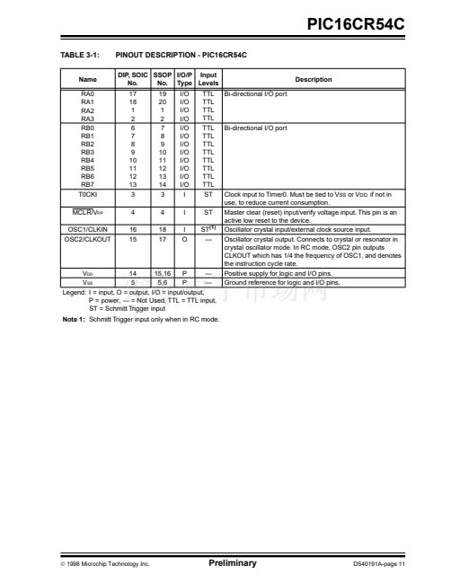
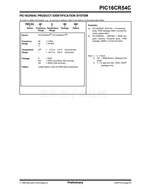
PIC16CR54C
Pin Diagrams
PDIP and SOIC
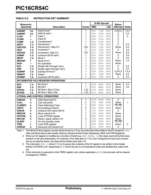
RA2
RA3
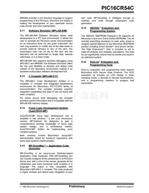
T0CKI
MCLRV
PP
V
SS
RB0
RB1
RB2
RB3
鈥?
2
3
4
5
6
7
8
9
18
17
16
15
14
13
12
11
10
RA1
RA0
OSC1/CLKIN
OSC2/CLKOUT
V
DD
RB7
RB6
RB5
RB4
ROM-Based 8-Bit CMOS Microcontroller Series
Devices Included in this Data Sheet:
High-Performance RISC CPU:
鈥?Only 33 single word instructions to learn
鈥?All instructions are single cycle (200 ns) except for
program branches which are two-cycle
鈥?Operating speed: DC - 20 MHz clock input
DC - 200 ns instruction cycle
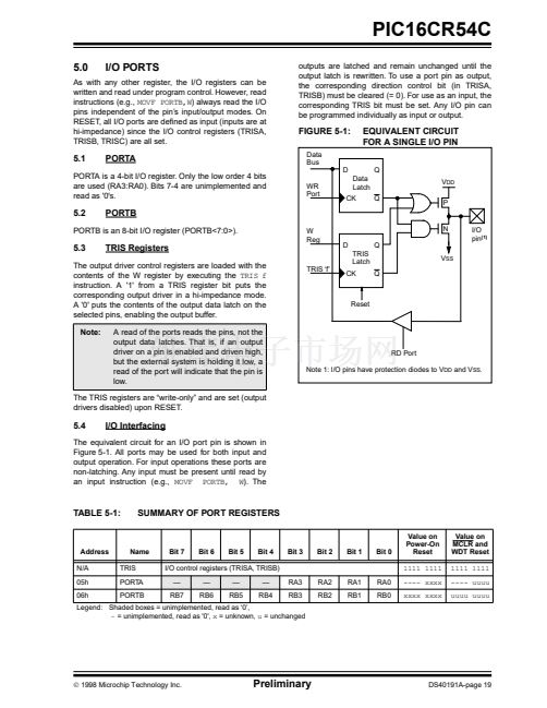
I/O
ROM
RAM
PIC16CR54C
PIC16CR54C
18
12
512
25
鈥?12-bit wide instructions
鈥?8-bit wide data path
鈥?Seven or eight special function hardware registers
鈥?Two-level deep hardware stack
鈥?Direct, indirect and relative addressing modes for
data and instructions
SSOP
RA2
RA3
T0CKI
MCLRV
PP
V
SS
V
SS
RB0
RB1
RB2
RB3
鈥?
2
3
4
5
6
7
8
9
10
20
19
18
17
16
15
14
13
12
11
RA1
RA0
OSC1/CLKIN
OSC2/CLKOUT
V
DD
V
DD
RB7
RB6
RB5
RB4
Peripheral Features:
鈥?8-bit real time clock/counter (TMR0) with 8-bit
programmable prescaler
鈥?Power-On Reset (POR)
鈥?Device Reset Timer (DRT)
鈥?Watchdog Timer (WDT) with its own on-chip
RC oscillator for reliable operation
鈥?Programmable code-protection
鈥?Power saving SLEEP mode
鈥?Selectable oscillator options:
- RC:
Low-cost RC oscillator
- XT:
Standard crystal/resonator
- HS:
High-speed crystal/resonator
- LP:
Power saving, low-frequency crystal
PIC16CR54C
CMOS Technology:
鈥?Low-power, high-speed CMOS ROM technology
鈥?Fully static design
鈥?Wide-operating voltage and temperature range:
- ROM Commercial/Industrial 3.0V to 5.5V
鈥?Low-power consumption
- < 2 mA typical @ 5V, 4 MHz
- 15
碌A
typical @ 3V, 32 kHz
- < 0.6
碌A
typical standby current
(with WDT disabled) @ 3V, 0掳C to 70掳C
漏
1998 Microchip Technology Inc.
Preliminary
DS40191A-page 1


 1
1
 2
2
 3
3
 4
4
 5
5
 6
6
 7
7
 8
8
 9
9
 10
10
 11
11
 12
12
 13
13
 14
14
 15
15
 16
16
 17
17
 18
18
 19
19
 20
20
 21
21
 22
22
 23
23
 24
24
 25
25
 26
26
 27
27
 28
28
 29
29
 30
30
 31
31
 32
32
 33
33
 34
34
 35
35
 36
36
 37
37
 38
38
 39
39
 40
40
 41
41
 42
42
 43
43
 44
44
 45
45
 46
46
 47
47
 48
48
 49
49
 50
50
 51
51
 52
52
 53
53
 54
54
 55
55
 56
56
 57
57
 58
58
 59
59
 60
60
 61
61
 62
62
 63
63
 64
64
 65
65
 66
66
 67
67
 68
68
 69
69
 70
70
 71
71
 72
72
 73
73
 74
74
 75
75
 76
76
 77
77
 78
78
 79
79
 80
80
 81
81
 82
82
 83
83
 84
84
