|
|||||||||||
| 技术交流 | 电路欣赏 | 工控天地 | 数字广电 | 通信技术 | 电源技术 | 测控之家 | EMC技术 | ARM技术 | EDA技术 | PCB技术 | 嵌入式系统 驱动编程 | 集成电路 | 器件替换 | 模拟技术 | 新手园地 | 单 片 机 | DSP技术 | MCU技术 | IC 设计 | IC 产业 | CAN-bus/DeviceNe |
自己试着翻译了一个三电平同步脉冲的短文,请大家指正! |
| 作者:ywm2008ic 栏目:数字广电 |
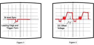
为什么HDTV使用三电平同步? 作者:Dave Pincek The advent of HDTV has brought a NUMBER of new concepts and TECHNOLOGIES with it. One of the concepts put into practice is tri-level sync. Tri-level sync solves some traditional problems found with bi-level sync. Although tri-level sync is preferable with the new television SYSTEM, we still find ourselves interfacing to SYSTEMs capable of HANDLING ONLY bi-level sync. Therefore, the need exists to convert from tri-level to bi-level sync on occasion. This Tech Corner will acquaint the reader with the new tri-level sync format and its relationship to bi-level sync. HDTV的到来也带来了许多新的概念和技术,其中之一就是三电平同步。三电平同步解决了一些过去在双电平同步时出现的问题。尽管三电平同步在新的电视系统中使用较多,我们发现仍然需要同时考虑那些仅使用双电平同步的系统。所以,有时候需要把三电平的同步信号转换为双电平的同步信号。这份“技术角”将要使读者了解三电平的同步信号格式以及它与双电平的同步信号的关系。 Bi-Level Sync Bi-level sync has been the STANDARD synchronization signaling method for all forms of VIDEO including COMPUTER VIDEO, composite VIDEO, S-VIDEO, and component VIDEO. Bi-level refers to two levels. For sync, this means a PULSE having two voltage levels (a high and low level, relatively speaking), hence the NAME. Systems using bi-level sync are edge triggered. Typically, the negative-going, leading edge of the PULSE triggers the synchronization PROCESS (Figure 1). DISPLAY SYSTEMs must "look" for this negative going edge in order to identify the moment in time when to re-sync the raster scan PROCESS. Most will recall that COMPUTER graphic cards sometimes OUTPUT positive-going sync. Positive-going sync signal the DISPLAY that the graphics LINE rate has changed to a new format. 对于几乎所有格式的视频信号(如计算机输出的视频信号、复合视频、S端子视频和分量视频)来说,双电平同步已经成为了一个标准的同步信号格式。双电平指的就是两个电平,对于同步信号来说,顾名思义,这意味着一个脉冲包含了两个电平值(相对而言,就是一个高电平和一个低电平)。系统中使用的双同步电平是沿触发的。一般来讲,负极性的、沿触发的脉冲信号会触发一个同步过程(如图1)。显示系统必须“找到”这个负极性的下降沿,以便确定重新同步光栅扫描进程的时刻。更多时候还需要计算机显卡产生一个正极性触发的同步信号,它会通知显示终端所显示的图像行频已经改变到一个新的格式了。 Looking for the sync PULSE has always been one of the "trickiest" of tasks for the DISPLAY signal PROCESSor. It requires careful biasing of the sync PROCESSing circuitry so that the sync PULSE is made as distinguishable as possible from the other voltage levels within the VIDEO signal. As PART of the VIDEO signal, bi-level sync introduces an unwanted DC component (Figure 2). In PROCESSing of composite, S-VIDEO, or component VIDEO the DC component is not too troublesome and can easily be managed as PART of the normal sync separation routine. When bi-level sync is introduced onto RGB VIDEO channels, the PROCESS is more complex. In some SYSTEMs, sync is introduced on the GREEN channel ONLY. This requires that the sync separation PROCESS be ultra clean; in most cases, however, it is not. Usually a very narrow sync PULSE remains. 对于显示信号处理器来说,寻找同步脉冲一直都是一项十分重要的工作。为了能够方便的将同步脉冲从包含着许多其他电平分量的视频信号中区分出来,需要仔细设计同步信号处理电路。作为视频信号的一部分,双电平同步包含了一部分并不需要的直流分量(如图2)。在对复合视频信号、S端子信号或者是分量信号的处理过程中,直流分量并非难以处理,它能够在通常的同步分离过程中被进行处理掉。当双电平同步被引入RGB视频信号通道后,处理过程就变得复杂了。在一些系统中,同步信号只是叠加在绿色通道上面,这就要求同步分离电路相当出色,但在大多情况下其实并不如意。通常只会有较窄的同步脉冲被分离出来。 Residual sync results from incomplete removal of the sync information from a VIDEO PROCESSing channel. Sync is typically imposed on the GREEN channel in RGsB SYSTEMs. High definition component VIDEO signals contain sync on each channel.!Depending on the performance characteristics of the DC restoration circuitry within the VIDEO PROCESSing channel, some or all of the sync PULSE may not be removed from the GREEN channel. Residual sync causes the GREEN channel to bias incorrectly with respect to red and BLUE at the DISPLAY CRT, thus causing a color shift. Even in RGB SYSTEMs where sync is introduced on all three channels, there is some difficulty with maintaining consistent PROCESSing between the three channels. Again, small DC shifts in the black level caused by residual sync can disturb the color balance or gains of the VIDEO channels. 剩下的同步信息均是来源于视频处理通道的不完整的同步信息。同步信息通常附加在RGsB系统中的绿色通道中。高分辨率的分量视频信号在其每一个通道中都包含了同步信息!根据视频处理通道中的直流电平恢复电路的性能,部分或全部的同步脉冲不会从绿色通道中移除。剩余的同步信息将使绿色通道无法与CRT显示所需的红色和蓝色通道相匹配,因而会导致色偏。即使在RGB系统中三个通道中都有同步信息,在保持三个通道处理的一致时仍会有一些困难。同样,由于残留的同步信号而导致的黑电平上很小的直流偏移依然能够影响颜色的平衡和各个视频通道的增益。 A significant amount of POWER is used by the broadcast transmitter to send the sync PULSE. Polarity of the VIDEO signal is designed to minimize the amount of POWER used to transmit sync. And, while we have not transmitted ANALOG versions of high definition television terrestrially, early testing done during HDTV development demonstrated a need to improve the management of synchronization in the new television SYSTEM. Tri-level sync eliminates the DC component and provides a more robust way to identify the coming of synchronization in the signal chain. 由于大量的功率被广播发射机用来发送同步脉冲,一般将视频信号的极性设计为在传送同步信号降低功耗的方式。同时,我们在地面广播中到目前也没有传送高清电视信号的版本。早期在HDTV开发中完成的测试证明,在新的电视系统中需要改进同步信号的处理方式。三电平同步方式消除了直流分量,提供了更有效的办法来确定同步信号在信号链的位置。 Tri-Level Sync Tri-level sync was introduced with the SMPTE 240 ANALOG HDTV STANDARD. Previous to that, the early HDTV 1125/60 SYSTEMs used various synchronization waveforms, as provided by various 1125/60 EQUIPMENT manufacturers. The creators of the later SMPTE 240 HDTV STANDARD searched for a STANDARD sync waveform that would ensure SYSTEM compatibility. The goal was to provide more precise synchronization and relative timing of the three component VIDEO signals. HDTV component VIDEO has sync present on all three channels: Y, Pb, and Pr. In addition, the sync structure needs to be resilient enough to endure multigenerational recording and other noisy situations. Tri-level sync met the requirements. 在模拟高清晰度电视标准SMPTE240中引入了三电平同步。在过去,由于众多不同的1125/60仪器制造商的出现,早期的HDTV 1125/60系统使用了很多中同步波形。后来SMPTE 240 HDTV标准的出现确立了一个标准的同步信号波形,确保了系统的兼容性。目标是提供更为精确的同步信息及相关的三个分量视频信号的时序。HDTV分量视频信号的Y、Pb、Pr三个通道中均有同步信号。同时,同步信号的构成方式需要足够可靠有效并承受持续长期的充满噪声的环境。三电平同步正好满足了这个要求。 Figure 3 shows a graphic representation of a tri-level sync signal. As defined by the SMPTE 240 STANDARD, the PULSE will start at the |
| 2楼: | >>参与讨论 | ||
| 作者: iC921 于 2006/3/11 2:50:00 发布:
Tri-Level Sync in a Bi-Level World Tri-Level Sync in a Bi-Level Worldby Dave Pincek, Vice President of PRODUCT Development The advent of HDTV has brought a NUMBER of new concepts and TECHNOLOGIES with it. One of the concepts put into practice is tri-level sync. Tri-level sync solves some traditional problems found with bi-level sync. Although tri-level sync is preferable with the new television SYSTEM, we still find ourselves interfacing to SYSTEMs capable of HANDLING ONLY bi-level sync. Therefore, the need exists to convert from tri-level to bi-level sync on occasion. This Tech Corner will acquaint the reader with the new tri-level sync format and its relationship to bi-level sync. Bi-Level SyncBi-level sync has been the STANDARD synchronization signaling method for all forms of VIDEO including COMPUTER VIDEO, composite VIDEO, S-VIDEO, and component VIDEO. Bi-level refers to two levels. For sync, this means a PULSE having two voltage levels (a high and low level, relatively speaking), hence the NAME. Systems using bi-level sync are edge triggered. Typically, the negative-going, leading edge of the PULSE triggers the synchronization PROCESS (Figure 1). DISPLAY SYSTEMs must "look" for this negative going edge in order to identify the moment in time when to re-sync the raster scan PROCESS. Most will recall that COMPUTER graphic cards sometimes OUTPUT positive-going sync. Positive-going sync signal the DISPLAY that the graphics LINE rate has changed to a new format.Looking for the sync PULSE has always been one of the "trickiest" of tasks for the DISPLAY signal PROCESSor. It requires careful biasing of the sync PROCESSing circuitry so that the sync PULSE is made as distinguishable as possible from the other voltage levels within the VIDEO signal. As PART of the VIDEO signal, bi-level sync introduces an unwanted DC component (Figure 2). In PROCESSing of composite, S-VIDEO, or component VIDEO the DC component is not too troublesome and can easily be managed as PART of the normal sync separation routine. When bi-level sync is introduced onto RGB VIDEO channels, the PROCESS is more complex. In some SYSTEMs, sync is introduced on the GREEN channel ONLY. This requires that the sync separation PROCESS be ultra clean; in most cases, however, it is not. Usually a very narrow sync PULSE remains.
Residual sync results from incomplete removal of the sync information from a VIDEO PROCESSing channel. Sync is typically imposed on the GREEN channel in RGsB SYSTEMs. High definition component VIDEO signals contain sync on each channel. Depending on the performance characteristics of the DC restoration circuitry within the VIDEO PROCESSing channel, some or all of the sync PULSE may not be removed from the GREEN channel. Residual sync causes the GREEN channel to bias incorrectly with respect to red and BLUE at the DISPLAY CRT, thus causing a color shift. Even in RGB SYSTEMs where sync is introduced on all three channels, there is some difficulty with maintaining consistent PROCESSing between the three channels. Again, small DC shifts in the black level caused by residual sync can disturb the color balance or gains of the VIDEO channels. A significant amount of POWER is used by the broadcast transmitter to send the sync PULSE. Polarity of the VIDEO signal is designed to minimize the amount of POWER used to transmit sync. And, while we have not transmitted ANALOG versions of high definition television terrestrially, early testing done during HDTV development demonstrated a need to improve the management of synchronization in the new television SYSTEM. Tri-level sync eliminates the DC component and provides a more robust way to identify the coming of synchronization in the signal chain. Tri-Level SyncTri-level sync was introduced with the SMPTE 240 ANALOG HDTV STANDARD. Previous to that, the early HDTV 1125/60 SYSTEMs used various synchronization waveforms, as provided by various 1125/60 EQUIPMENT manufacturers. The creators of the later SMPTE 240 HDTV STANDARD searched for a STANDARD sync waveform that would ensure SYSTEM compatibility. The goal was to provide more precise synchronization and relative timing of the three component VIDEO signals. HDTV component VIDEO has sync present on all three channels: Y, Pb, and Pr. In addition, the sync structure needs to be resilient enough to endure multigenerational recording and other noisy situations. Tri-level sync met the requirements.
Figure 3 shows a graphic representation of a tri-level sync signal. As defined by the SMPTE 240 STANDARD, the PULSE will start at the zero volts (specified black level) and first transitions negative, to -300 mV (+/- 6 mV). After a specified period, it transitions positive + 300 mV (+/- 6 mV), holds for a specified period and then returns to zero or black level. The DISPLAY SYSTEM "looks" for the zero crossing of the sync PULSE. Each half of the tri-level sync PULSE is defined to be 44 samples (reference clock periods) wide, for a total sync PULSE width of 88 samples. The rise time is defined to be four samples wide +/- 1.5 samples. This symmetry of design results in a net DC VALUE of zero volts. This is one major advantage of tri-level sync. This solves the problem of a bi-level signal introducing a DC component into the VIDEO signal. The elimination of DC offset makes signal PROCESSing easier. Within our new DIGITAL television SYSTEM, the unique excursions of the sync derive numerical VALUEs that are easily coded and easily recognized within the DIGITAL transmission channel. Converting Tri-Level to Bi-Level SyncThere are times when it is necessary to convert tri-level sync to bi-level sync such as when component HDTV is converted to RGBHV. A format converter, like Extron's CVC 200, will perform the conversion of tri-level to bi-level sync as PART of the component HDTV to RGB conversion PROCESS. Traditional DISPLAYs and projectors not capable of HANDLING tri-level sync will "see" sync information in the traditional way.Any time signals are converted from one format to another, the relative timing of the conversion is of prime importance. The introduction of timing error, once introduced into a signal channel, is difficult to REPAIR. The positioning of tri-level sync with respect to active VIDEO and the wider excursion from peak negative (-300 mV) to peak positive (+300 mV) provided by this format establishes easier sync detection and more consistent triggering through the use of the zero crossing. When converting bi-level sync, the leading edge of the bi-level PULSE should be aligned using the zero crossing of the tri-level sync. By doing so, the bi-level sync PULSE will provide leading-edge trigger at the proper point and correct timing will be maintained. Figure 4 shows the relationship of a tri-level sync signal to a properly-timed bi-level sync signal. Anyone involved in interfacing VIDEO signals will, at some point, encounter the need to convert tri-level sync to bi-level sync. As time progresses, a growing GROUP of DISPLAYs and projectors will be designed to cope directly with these format differences. In the meantime, technicians should be aware of the differences in sync construction and the proper timing relationship for conversion between these two common formats. |
|||

| 3楼: | >>参与讨论 |
| 作者: iC921 于 2006/3/11 3:06:00 发布:
链接 |
|
| 4楼: | >>参与讨论 |
| 作者: ywm2008ic 于 2006/3/13 22:05:00 发布:
谢谢ic921 对,就是这篇文章,我看了觉得还是有点收获,所以一时兴起就试着翻了一下。可惜后面图没贴上去,遗憾遗憾。 倒是谢谢ic921帮了我这个忙了。 :) |
|
| 5楼: | >>参与讨论 |
| 作者: iC921 于 2006/3/13 23:15:00 发布:
不用谢 我也是看了没图就把它找出来的。 我不知道GOOLE翻译在哪了,回来找一下。有兴趣到模拟多多参与我们的翻译。 |
|
|
|
| 免费注册为维库电子开发网会员,参与电子工程师社区讨论,点此进入 |
Copyright © 1998-2006 www.dzsc.com 浙ICP证030469号 |