YA962S6R
(Ip 10A / 600V)
[200510]
(For PFC circut)
(current continuous mode)
LOW LOSS SUPER HIGH SPEED RECTIFIER
Super LLD
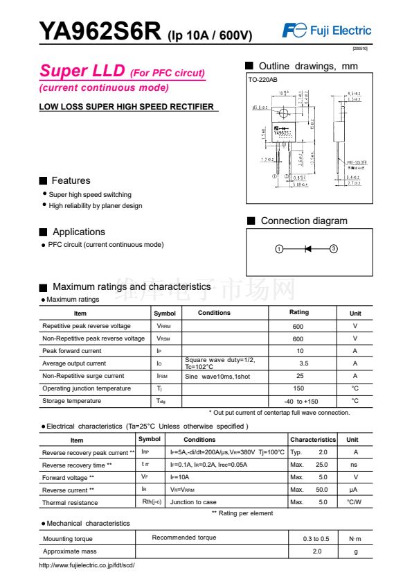
Outline drawings, mm
TO-220AB
2
Features
Super high speed switching
High reliability by planer design
Connection diagram
Applications
PFC circuit (current continuous mode)
1
3
Maximum ratings and characteristics
Maximum ratings
Item
Repetitive peak reverse voltage
Non-Repetitive peak reverse voltage
Peak forward current
Average output current
Non-Repetitive surge current
Operating junction temperature
Storage temperature
Symbol
V
RRM
V
RSM
I
P
I
O
I
FSM
T
j
T
stg
Square wave duty=1/2,
Tc=102掳C
Sine wave10ms,1shot
Conditions
Rating
600
600
10
3.5
25
150
-40 to +150
* Out put current of centertap full wave connection.
Unit
V
V
A
A
A
掳C
掳C
Electrical characteristics (Ta=25掳C Unless otherwise specified )
Item
Reverse recovery peak current **
Reverse recovery time **
Forward voltage **
Reverse current **
Thermal resistance
Symbol
I
RP
t
rr
V
F
I
R
R
th(j-c)
Conditions
Characteristics
2.0
25.0
5.0
50.0
5.0
Unit
A
ns
V
碌A
掳C/W
I
F
=5A,-di/dt=200A/碌s,V
R
=380V Tj=100掳C Typ.
I
F
=0.1A, I
R
=0.2A, I
rec
=0.05A
I
F
=10A
V
R
=V
RRM
Junction to case
** Rating per element
Max.
Max.
Max.
Max.
Mechanical characteristics
Mouunting torque
Approximate mass
http://www.fujielectric.co.jp/fdt/scd/
Recommended torque
0.3 to 0.5
2.0
N路m
g


 1
1
 2
2
 3
3
