FlashFlex51 MCU
SST89C54 / SST89C58
Preliminary Specifications
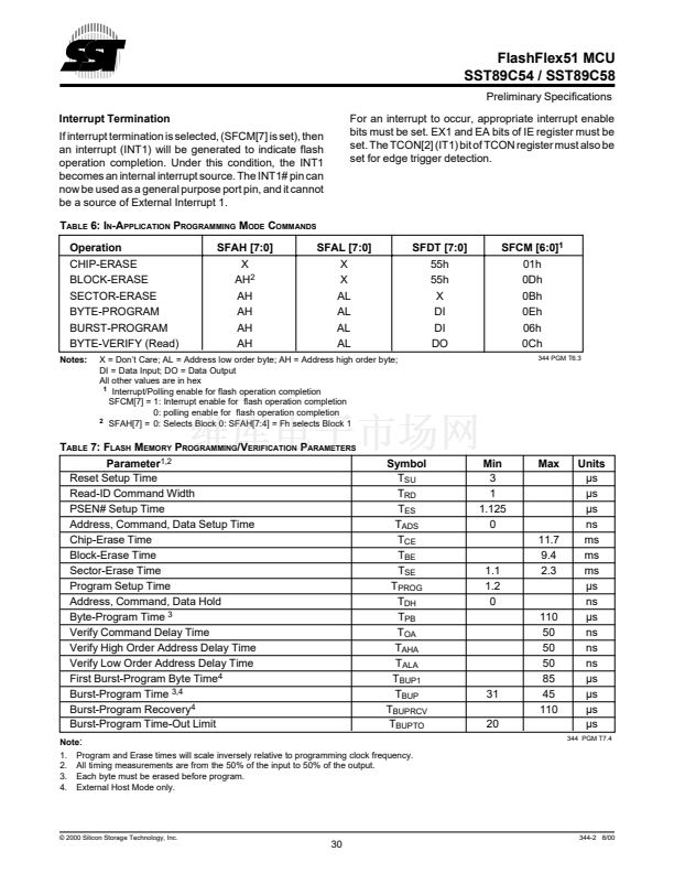
Interrupt Termination
If interrupt termination is selected, (SFCM[7] is set), then
an interrupt (INT1) will be generated to indicate flash
operation completion. Under this condition, the INT1
becomes an internal interrupt source. The INT1# pin can
now be used as a general purpose port pin, and it cannot
be a source of External Interrupt 1.
T
ABLE
6: I
N
-A
PPLICATION
P
ROGRAMMING
M
ODE
C
OMMANDS
Operation
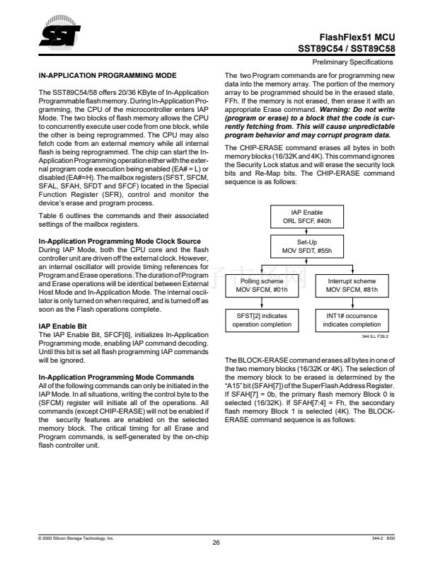
CHIP-ERASE
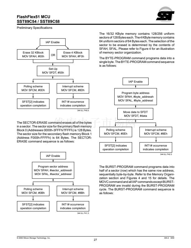
BLOCK-ERASE
SECTOR-ERASE
BYTE-PROGRAM
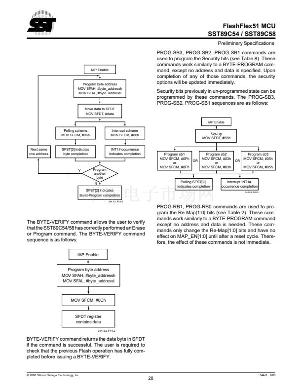
BURST-PROGRAM
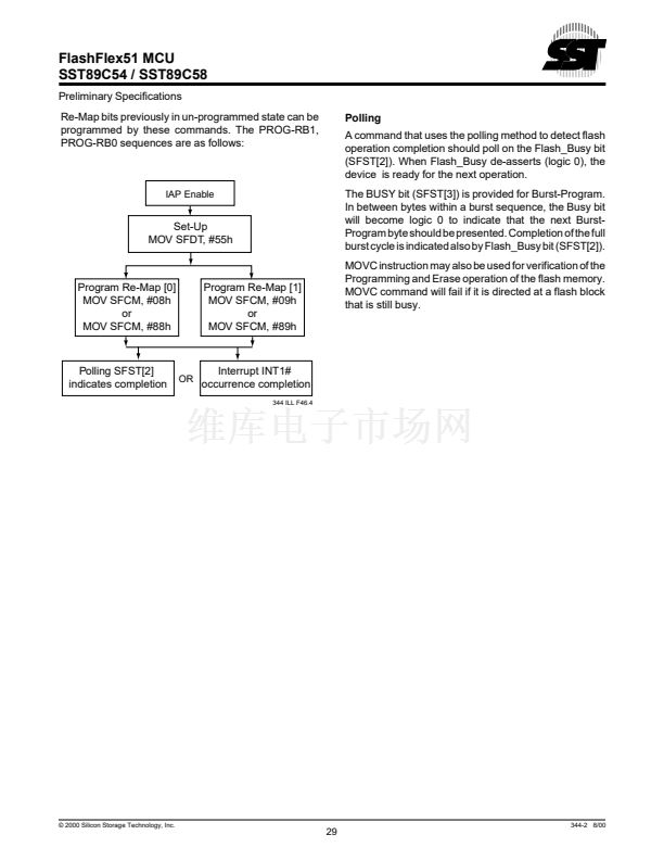
BYTE-VERIFY (Read)
Notes:
For an interrupt to occur, appropriate interrupt enable
bits must be set. EX1 and EA bits of IE register must be
set. The TCON[2] (IT1) bit of TCON register must also be
set for edge trigger detection.
SFAH [7:0]
X
AH
2
AH
AH
AH
AH
SFAL [7:0]
X
X
AL
AL
AL
AL
SFDT [7:0]
55h
55h
X
DI
DI
DO
SFCM [6:0]
1
01h
0Dh
0Bh
0Eh
06h
0Ch
344 PGM T6.3
X = Don鈥檛 Care; AL = Address low order byte; AH = Address high order byte;
DI = Data Input; DO = Data Output
All other values are in hex
1
Interrupt/Polling enable for flash operation completion
SFCM[7] = 1: Interrupt enable for flash operation completion
0: polling enable for flash operation completion
2
SFAH[7] = 0: Selects Block 0: SFAH[7:4] = Fh selects Block 1
T
ABLE
7: F
LASH
M
EMORY
P
ROGRAMMING
/V
ERIFICATION
P
ARAMETERS
Parameter
1,2
Reset Setup Time
Read-ID Command Width
PSEN# Setup Time
Address, Command, Data Setup Time
Chip-Erase Time
Block-Erase Time
Sector-Erase Time
Program Setup Time
Address, Command, Data Hold
Byte-Program Time
3
Verify Command Delay Time
Verify High Order Address Delay Time
Verify Low Order Address Delay Time
First Burst-Program Byte Time
4
Burst-Program Time
3,4
Burst-Program Recovery
4
Burst-Program Time-Out Limit
Symbol
T
SU
T
RD
T
ES
T
ADS
T
CE
T
BE
T
SE
T
PROG
T
DH
T
PB
T
OA
T
AHA
T
ALA
T
BUP1
T
BUP
T
BUPRCV
T
BUPTO
Min
3
1
1.125
0
Max
1.1
1.2
0
11.7
9.4
2.3
31
20
110
50
50
50
85
45
110
Units
碌s
碌s
碌s
ns
ms
ms
ms
碌s
ns
碌s
ns
ns
ns
碌s
碌s
碌s
碌s
344 PGM T7.4
Note
:
1. Program and Erase times will scale inversely relative to programming clock frequency.
2. All timing measurements are from the 50% of the input to 50% of the output.
3. Each byte must be erased before program.
4. External Host Mode only.
漏 2000 Silicon Storage Technology, Inc.
30
344-2 8/00


 1
1
 2
2
 3
3
 4
4
 5
5
 6
6
 7
7
 8
8
 9
9
 10
10
 11
11
 12
12
 13
13
 14
14
 15
15
 16
16
 17
17
 18
18
 19
19
 20
20
 21
21
 22
22
 23
23
 24
24
 25
25
 26
26
 27
27
 28
28
 29
29
 30
30
 31
31
 32
32
 33
33
 34
34
 35
35
 36
36
 37
37
 38
38
 39
39
 40
40
 41
41
 42
42
 43
43
 44
44
 45
45
 46
46
 47
47
 48
48
 49
49
 50
50
