FlashFlex51 MCU
SST89C54 / SST89C58
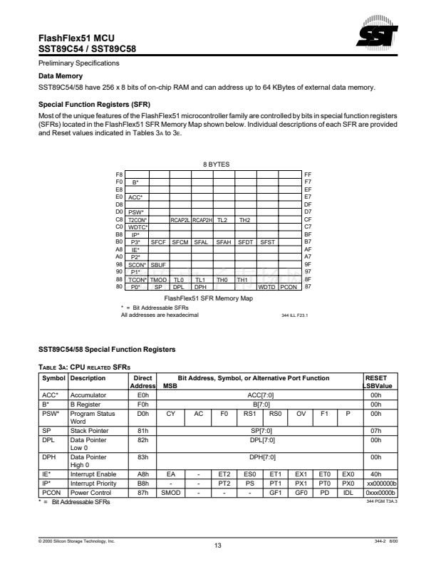
Preliminary Specifications
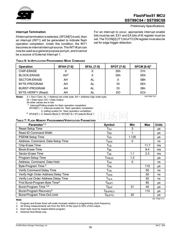
WATCHDOG TIMER
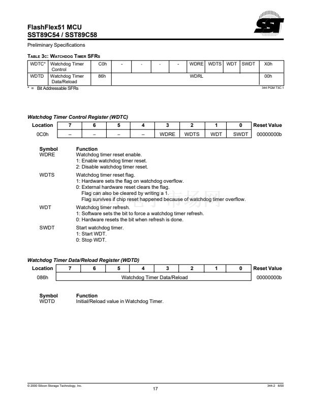
The SST89C54/58 offer an enhanced programmable
Watchdog Timer (WDT) for fail safe protection against
software deadlock and allows an automatic recovery.
To protect the system against software deadlock, the
user has to refresh the WDT within a user defined time
period. If the software fails to do this periodical refresh,
an internal hardware reset will be initiated. The software
can be designed such that the WDT times out if the
program does not work properly. It also times out if a
software error is based on the hardware related prob-
lems.
The WDT in the SST89C54/58 share the same time base
with the flash controller unit. When the flash controller
unit is operating, the time base will be re-started by the
hardware periodically, therefore delaying the time-out
period of the watchdog timer. The upper 8-bits of the time
base register are used as the reload register of the WDT.
The internal oscillator that drives the WDT operates
within a frequency range as shown in Table 11. Minimum
clock cycle for the WDT is 7.7ms.
Figure 18 provides a block diagram of the WDT. Two
SFRs (WDTC and WDTD) control watchdog timer op-
eration. During idle mode, WDT operation is temporarily
suspended, and resumes upon an interrupt exit from idle.
CLK
Counter
7.7 ms
min.
WDT Upper Byte
WDT Reset
Internal Reset
Ext. RST
WDTC
WDTD
344 ILL F10.2
F
IGURE
18: B
LOCK
D
IAGRAM OF
P
ROGRAMMABLE
W
ATCHDOG
T
IMER
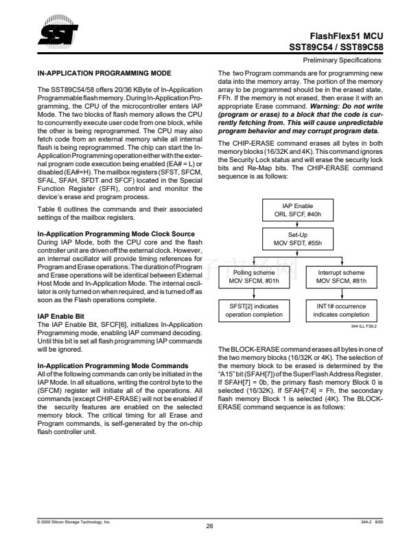
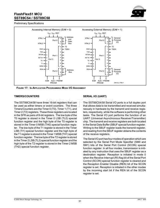
SECURITY LOCK
The Security feature protects against software piracy and
prevents the contents of the flash from being read by
unauthorized parties. It also protects against code corrup-
tion resulting from accidental erasing and programming to
the internal flash memory locations. There are two different
types of security locks in the SST89C54/58 security lock
system: Hard Lock and SoftLock.
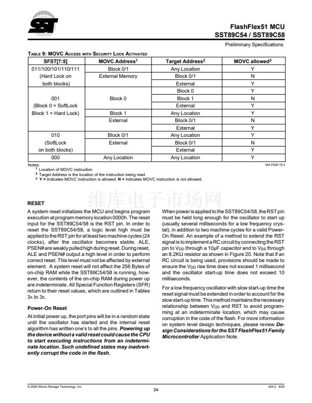
Hard Lock
When the Hard Lock is activated, the MOVC instructions
executed from Un-Locked or SoftLocked program address
space, are disabled from reading code bytes in Hard
Locked memory blocks (See Table 9). The Hard Lock can
either lock both flash memory blocks or just lock the upper
flash memory block (Block 1). All External Host and IAP
commands except for CHIP-ERASE are ignored for the
Hard Locked memory blocks.
SoftLock
SoftLock allows flash contents to be altered under a secure
environment. This lock option allows the user to update
program code in the Soft Locked memory block through In-
Application Programming Mode under a predetermined
secure environment. For example, if the Block 1 (4K)
memory block is locked, and the Block 0 (16K/32K)
memory block is Soft Locked, code residing in Block 1 can
program Block 0. The following IAP mode commands
issued through the command mailbox register, SFCM,
executed from a Hard Locked block can be operated on a
Soft Locked block: BLOCK-ERASE, SECTOR-ERASE,
BYTE-PROGRAM, BURST-PROGRAM and BYTE-
VERIFY.
In External Host Mode, SoftLock behaves the same as a
Hard Lock.
漏 2000 Silicon Storage Technology, Inc.
32
344-2 8/00


 1
1
 2
2
 3
3
 4
4
 5
5
 6
6
 7
7
 8
8
 9
9
 10
10
 11
11
 12
12
 13
13
 14
14
 15
15
 16
16
 17
17
 18
18
 19
19
 20
20
 21
21
 22
22
 23
23
 24
24
 25
25
 26
26
 27
27
 28
28
 29
29
 30
30
 31
31
 32
32
 33
33
 34
34
 35
35
 36
36
 37
37
 38
38
 39
39
 40
40
 41
41
 42
42
 43
43
 44
44
 45
45
 46
46
 47
47
 48
48
 49
49
 50
50
