DS2434
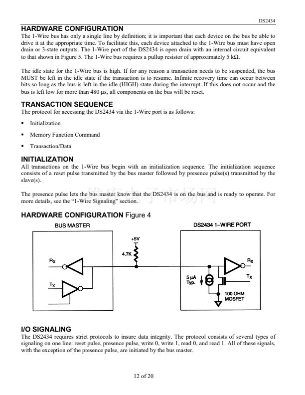
HARDWARE CONFIGURATION
The 1-Wire bus has only a single line by definition; it is important that each device on the bus be able to
drive it at the appropriate time. To facilitate this, each device attached to the 1-Wire bus must have open
drain or 3-state outputs. The 1-Wire port of the DS2434 is open drain with an internal circuit equivalent
to that shown in Figure 5. The 1-Wire bus requires a pullup resistor of approximately 5 k鈩?
The idle state for the 1-Wire bus is high. If for any reason a transaction needs to be suspended, the bus
MUST be left in the idle state if the transaction is to resume. Infinite recovery time can occur between
bits so long as the bus is left in the idle (HIGH) state during the interrupt. If this does not occur and the
bus is left low for more than 480
碌s,
all components on the bus will be reset.
TRANSACTION SEQUENCE
The protocol for accessing the DS2434 via the 1-Wire port is as follows:
Initialization
Memory Function Command
Transaction/Data
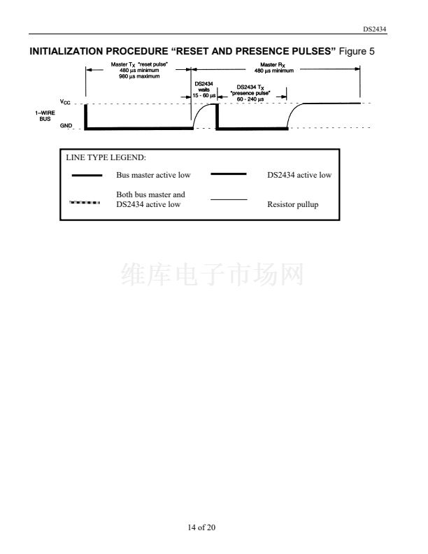
INITIALIZATION
All transactions on the 1-Wire bus begin with an initialization sequence. The initialization sequence
consists of a reset pulse transmitted by the bus master followed by presence pulse(s) transmitted by the
slave(s).
The presence pulse lets the bus master know that the DS2434 is on the bus and is ready to operate. For
more details, see the 鈥?-Wire Signaling鈥?section.
HARDWARE CONFIGURATION
Figure 4
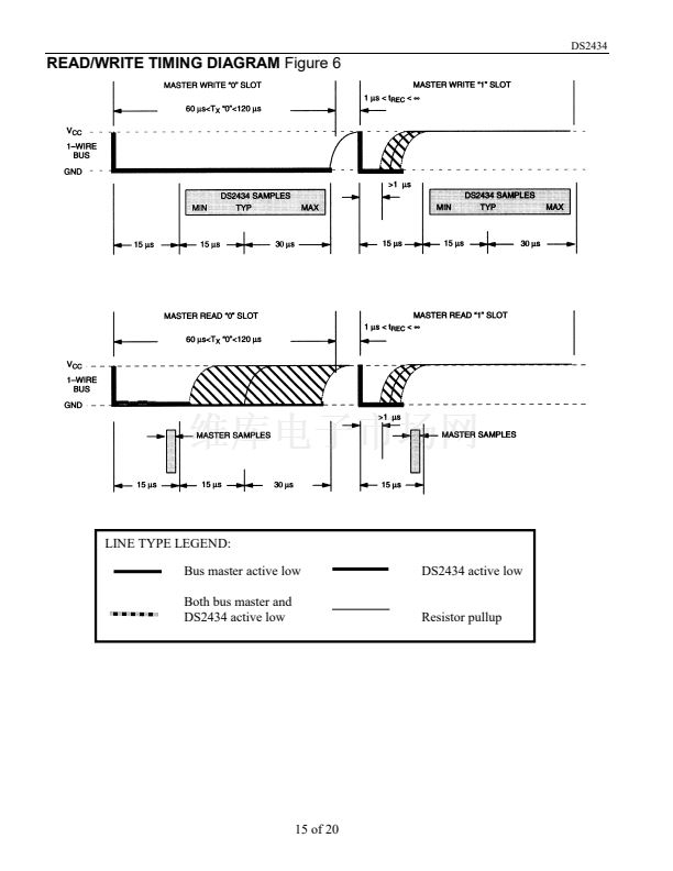
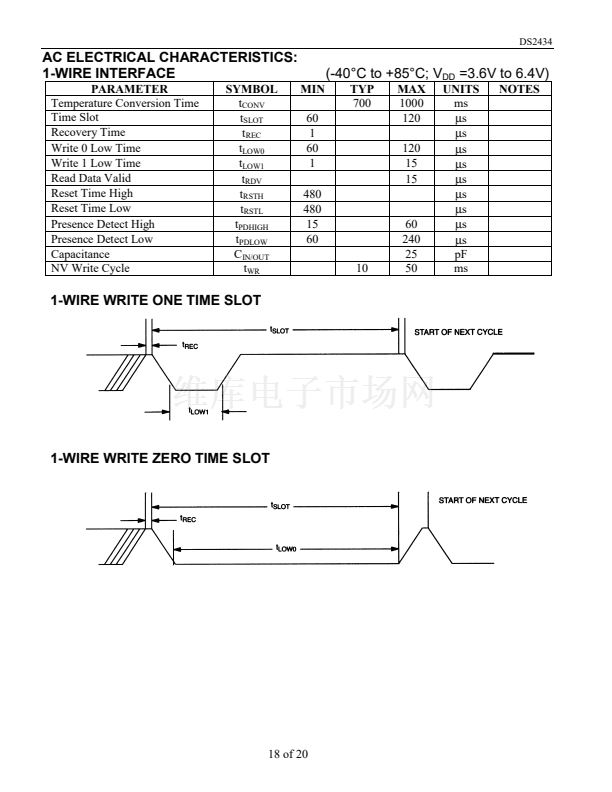
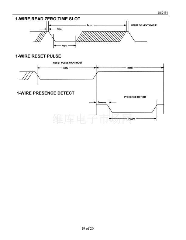
I/O SIGNALING
The DS2434 requires strict protocols to insure data integrity. The protocol consists of several types of
signaling on one line: reset pulse, presence pulse, write 0, write 1, read 0, and read 1. All of these signals,
with the exception of the presence pulse, are initiated by the bus master.
12 of 20


 1
1
 2
2
 3
3
 4
4
 5
5
 6
6
 7
7
 8
8
 9
9
 10
10
 11
11
 12
12
 13
13
 14
14
 15
15
 16
16
 17
17
 18
18
 19
19
 20
20
