隆 Semiconductor
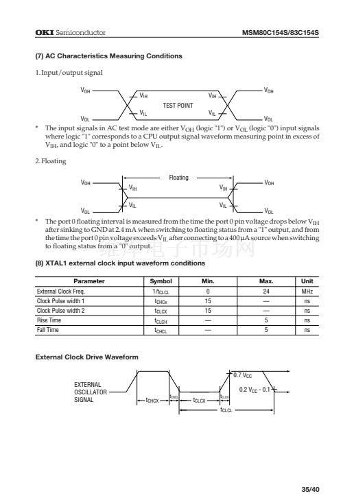
(7) AC Characteristics Measuring Conditions
1.Input/output signal
V
OH
V
IH
TEST POINT
V
OL
V
IL
V
IL
V
IH
MSM80C154S/83C154S
V
OH
V
OL
*
The input signals in AC test mode are either V
OH
(logic "1") or V
OL
(logic "0") input signals
where logic "1" corresponds to a CPU output signal waveform measuring point in excess of
V
IH
, and logic "0" to a point below V
IL
.
2.Floating
V
OH
Floating
V
IH
V
IL
V
IH
V
IL
V
OH
V
OL
V
OL
*
The port 0 floating interval is measured from the time the port 0 pin voltage drops below V
IH
after sinking to GND at 2.4 mA when switching to floating status from a "1" output, and from
the time the port 0 pin voltage exceeds V
IL
after connecting to a 400
mA
source when switching
to floating status from a "0" output.
(8) XTAL1 external clock input waveform conditions
Parameter
External Clock Freq.
Clock Pulse width 1
Clock Pulse width 2
Rise Time
Fall Time
Symbol
1/t
CLCL
t
CHCx
t
CLCX
t
CLCH
t
CHCL
Min.
0
15
15
鈥?/div>
鈥?/div>
Max.
24
鈥?/div>
鈥?/div>
5
5
Unit
MHz
ns
ns
ns
ns
External Clock Drive Waveform
0.7 V
CC
EXTERNAL
OSCILLATOR
SIGNAL
t
CHCL
0.2 V
CC
- 0.1
t
CLCX
t
CLCH
t
CHCX
t
CLCL
35/40


 1
1
 2
2
 3
3
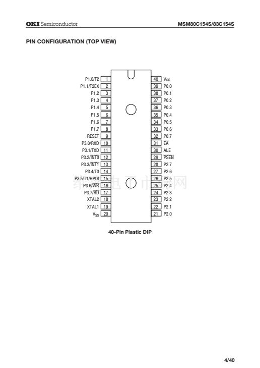 4
4
 5
5
 6
6
 7
7
 8
8
 9
9
 10
10
 11
11
 12
12
 13
13
 14
14
 15
15
 16
16
 17
17
 18
18
 19
19
 20
20
 21
21
 22
22
 23
23
 24
24
 25
25
 26
26
 27
27
 28
28
 29
29
 30
30
 31
31
 32
32
 33
33
 34
34
 35
35
 36
36
 37
37
 38
38
 39
39
 40
40
