Freescale Semiconductor, Inc.
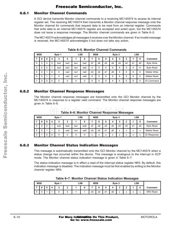
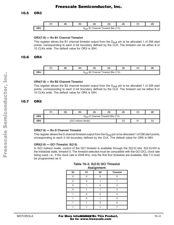
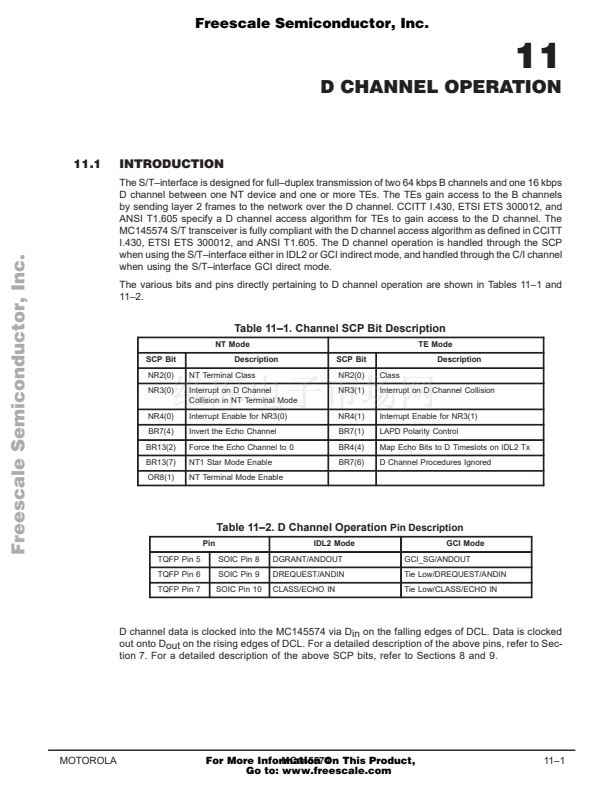
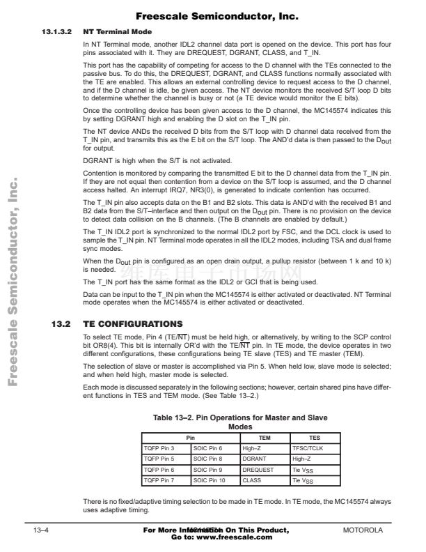
2.3
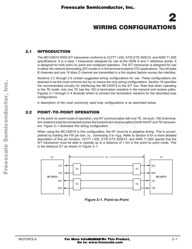
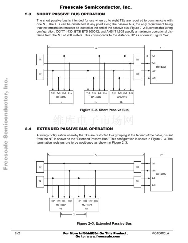
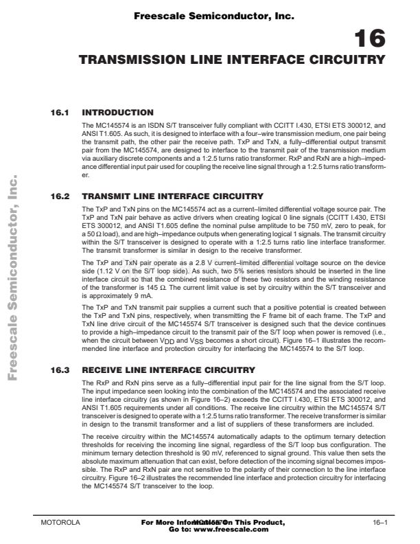
SHORT PASSIVE BUS OPERATION
The short passive bus is intended for use when up to eight TEs are required to communicate with
one NT. The TEs can be distributed at any point along the passive bus, the only requirement being
that the termination resistors be located at the end of the passive bus. Figure 2鈥? illustrates this wiring
configuration. CCITT I.430, ETSI ETS 300012, and ANSI T1.605 specify a maximum operational dis-
tance from the NT of 200 meters. This corresponds to the distance D2 as shown in Figure 2鈥?.
<
D2
>
TxP
NT
TR
TR
TxN
MC145574
RxP
Freescale Semiconductor, Inc...
TR
TR
RxN
TxP TxN RxP RxN
MC145574
TE
TxP TxN RxP RxN
MC145574
TE
TxP TxN RxP RxN
MC145574
TE
Figure 2鈥?. Short Passive Bus
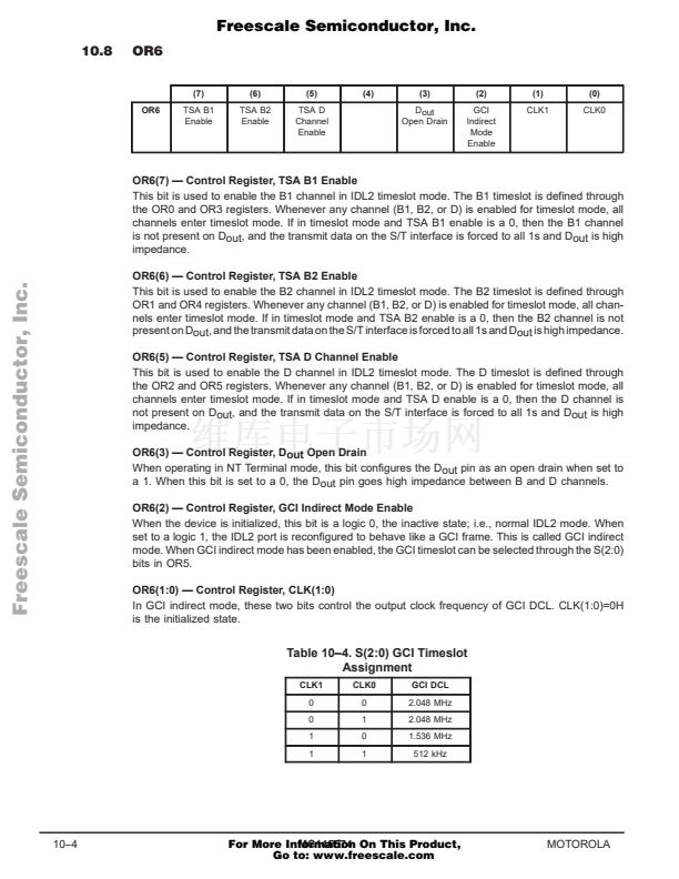
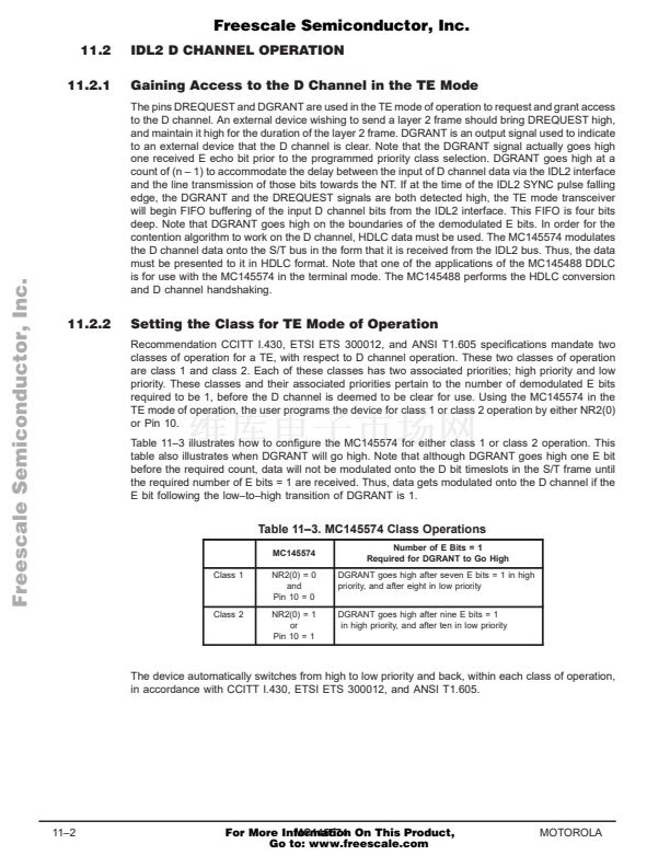
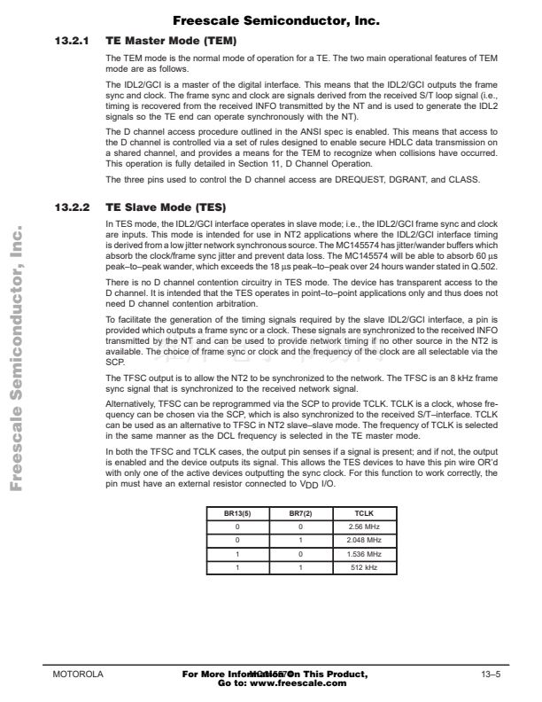
2.4
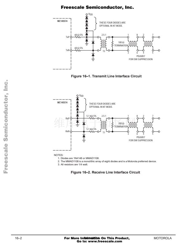
EXTENDED PASSIVE BUS OPERATION
A wiring configuration whereby the TEs are restricted to a grouping at the far end of the cable, distant
from the NT, is shown as the 鈥淓xtended Passive Bus.鈥?This configuration is shown in Figure 2鈥?. The
termination resistors are to be positioned as shown in Figure 2鈥?.
<
D4
>
TxP
NT
TR
TR
TxN
MC145574
RxP
TR
TR
RxN
TxP TxN RxP RxN
MC145574
TE
TxP TxN RxP RxN
MC145574
TE
D3
<
>
Figure 2鈥?. Extended Passive Bus
2鈥?
MC145574
For More Information On This Product,
Go to: www.freescale.com
MOTOROLA


 1
1
 2
2
 3
3
 4
4
 5
5
 6
6
 7
7
 8
8
 9
9
 10
10
 11
11
 12
12
 13
13
 14
14
 15
15
 16
16
 17
17
 18
18
 19
19
 20
20
 21
21
 22
22
 23
23
 24
24
 25
25
 26
26
 27
27
 28
28
 29
29
 30
30
 31
31
 32
32
 33
33
 34
34
 35
35
 36
36
 37
37
 38
38
 39
39
 40
40
 41
41
 42
42
 43
43
 44
44
 45
45
 46
46
 47
47
 48
48
 49
49
 50
50
 51
51
 52
52
 53
53
 54
54
 55
55
 56
56
 57
57
 58
58
 59
59
 60
60
 61
61
 62
62
 63
63
 64
64
 65
65
 66
66
 67
67
 68
68
 69
69
 70
70
 71
71
 72
72
 73
73
 74
74
 75
75
 76
76
 77
77
 78
78
 79
79
 80
80
 81
81
 82
82
 83
83
 84
84
 85
85
 86
86
 87
87
 88
88
 89
89
 90
90
 91
91
 92
92
 93
93
 94
94
 95
95
 96
96
 97
97
 98
98
 99
99
 100
100
 101
101
 102
102
 103
103
 104
104
 105
105
 106
106
 107
107
 108
108
 109
109
 110
110
 111
111
 112
112
 113
113
 114
114
 115
115
 116
116
 117
117
 118
118
 119
119
 120
120
 121
121
 122
122
 123
123
 124
124
 125
125
 126
126
 127
127
 128
128
 129
129
 130
130
 131
131
 132
132
 133
133
 134
134
 135
135
 136
136
 137
137
 138
138
 139
139
 140
140
 141
141
 142
142
 143
143
 144
144
 145
145
 146
146
 147
147
 148
148
 149
149
 150
150
 151
151
 152
152
 153
153
 154
154
 155
155
 156
156
 157
157
 158
158
 159
159
 160
160
 161
161
 162
162
 163
163
 164
164
