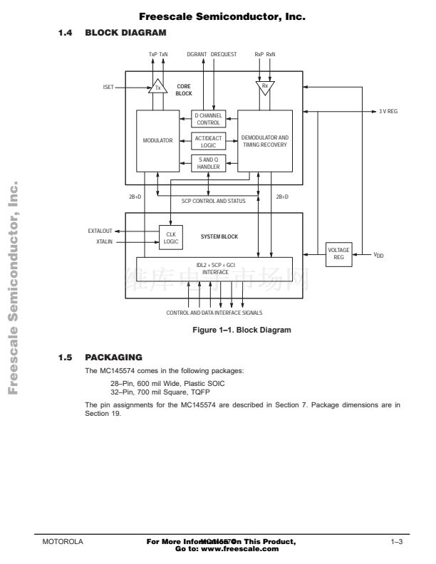
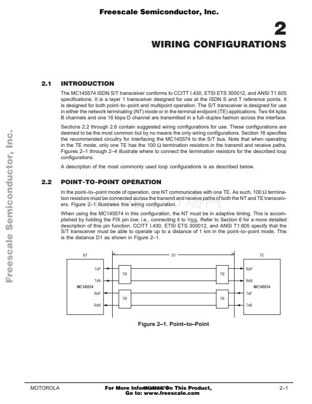
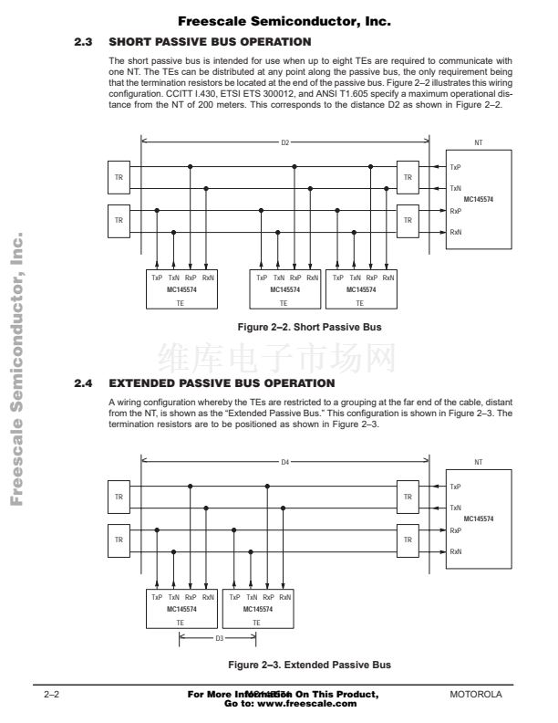
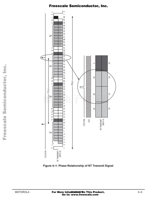
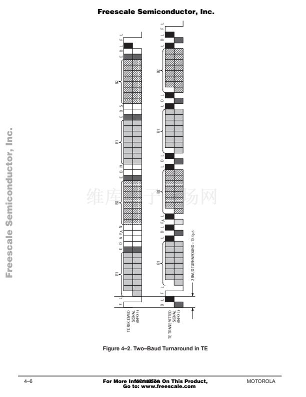
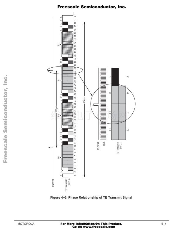
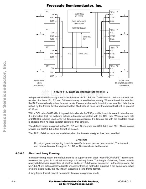
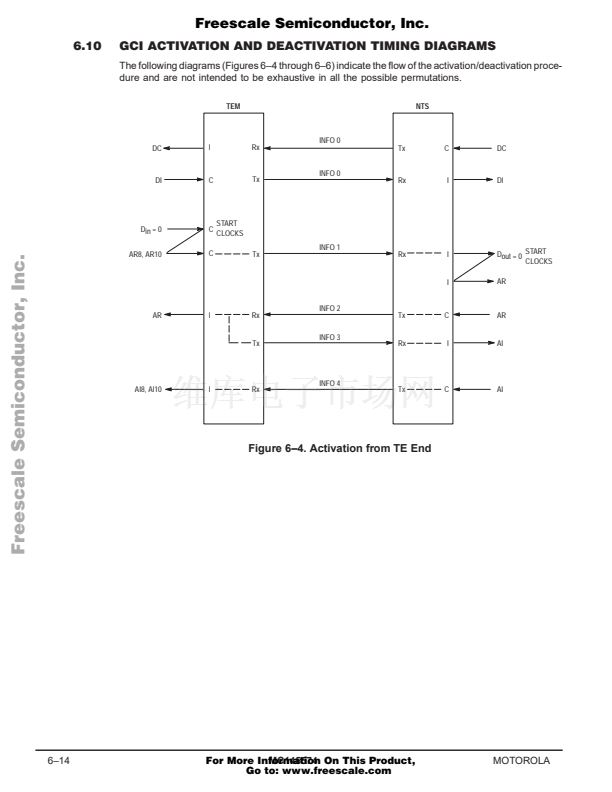
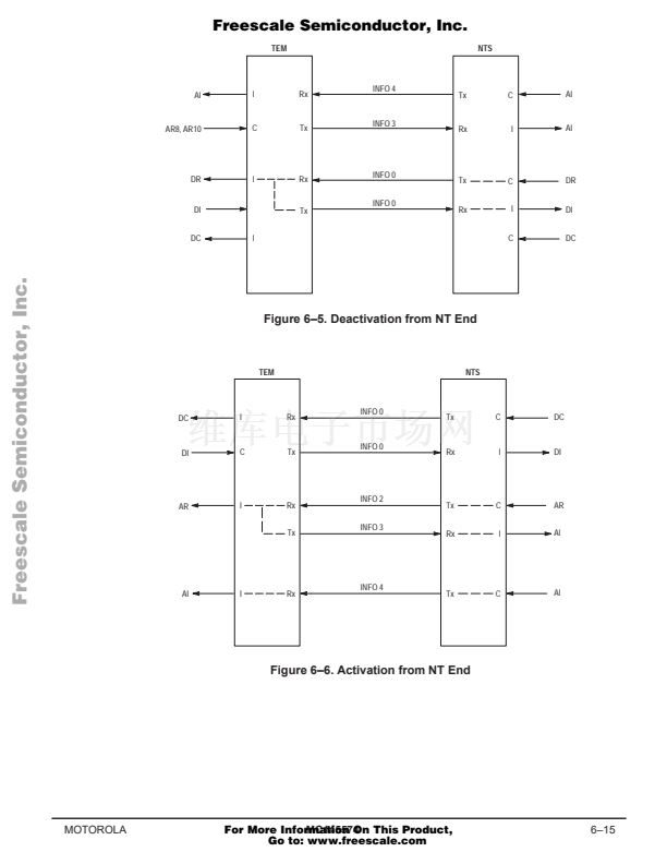
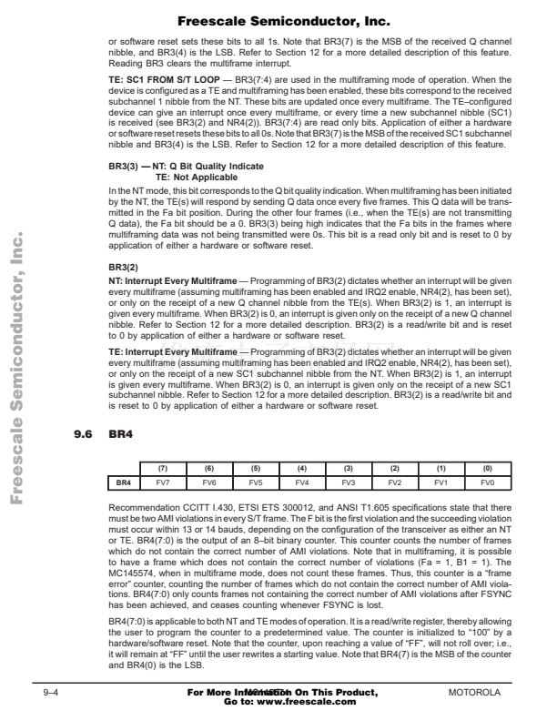
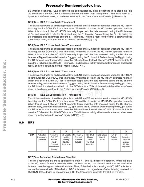
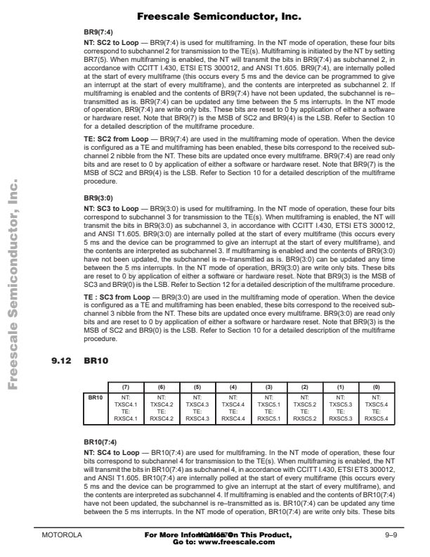
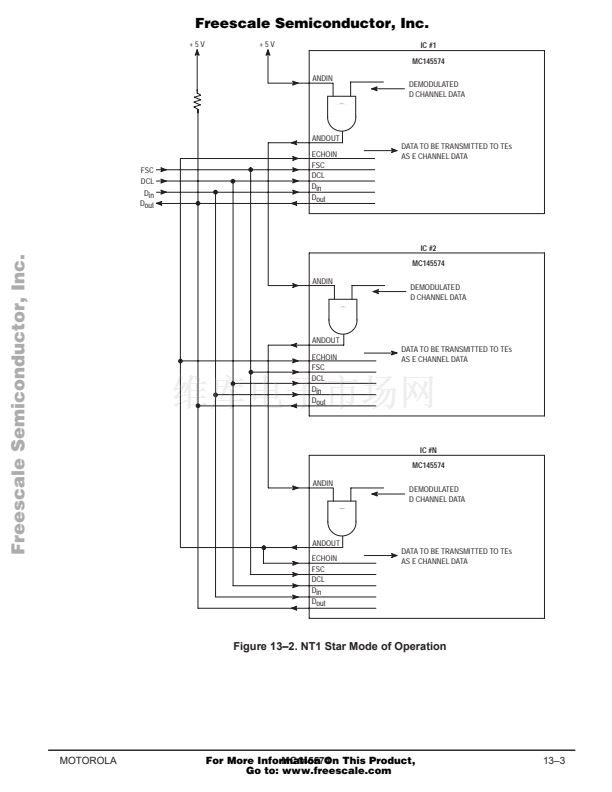
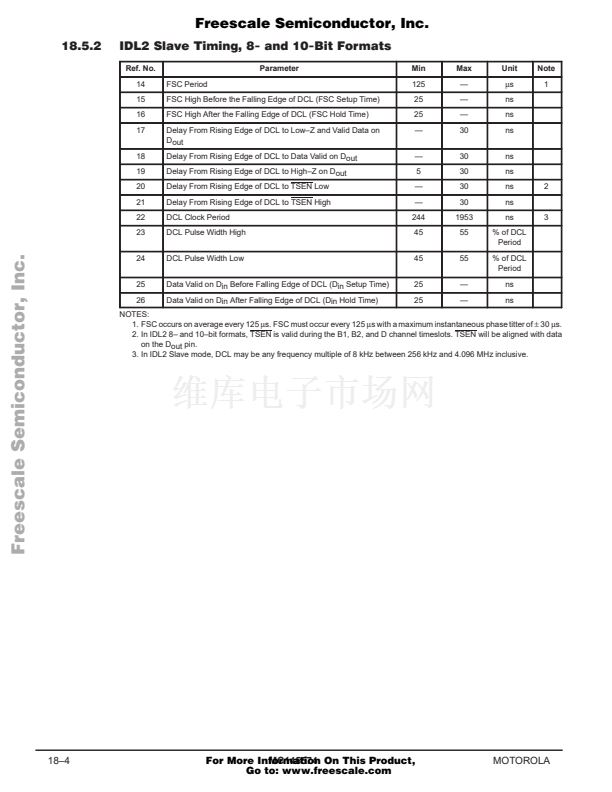
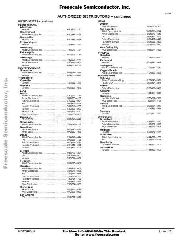
Freescale Semiconductor, Inc.
6.7.1
Monitor Channel Operation
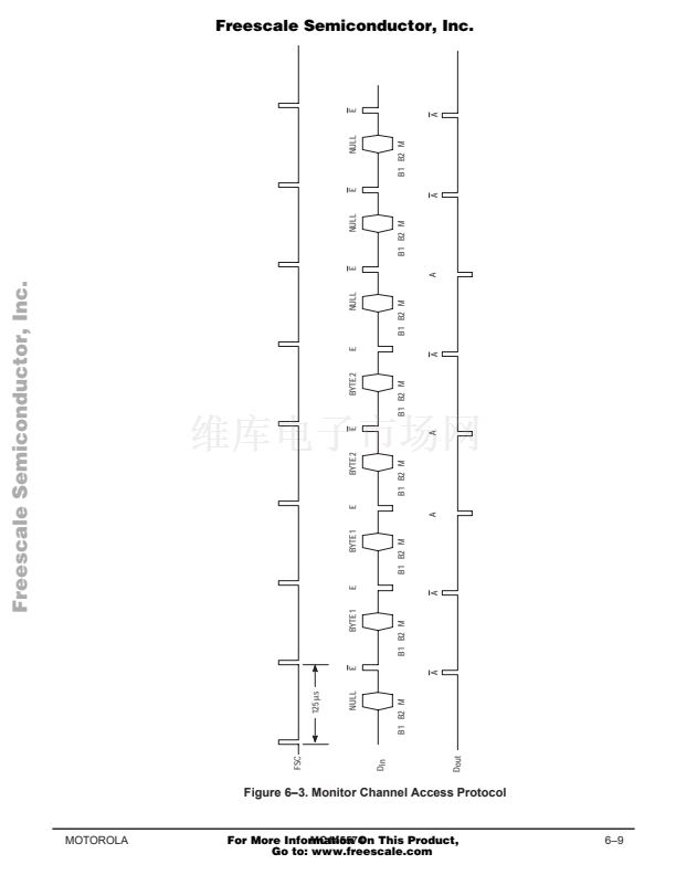
The Monitor channel is used to access the internal registers of the MC145574. All Monitor channel
messages are two bytes in length. Each byte is sent twice to permit the receiving GCI device to verify
data integrity. In ISDN applications, the Monitor channel is used for access to the S interface mainte-
nance messages. The entire register set of the MC145574 can be accessed via the Monitor channel.
The A and E bits in the GCI channel are used to control and acknowledge Monitor channel transfers
between the MC145574 and another GCI device. When the Monitor channel is inactive, the A and
E bit times from Dout are both high impedance. The A and E bits are active when they are driven
to VSS during their respective bit times. Pull鈥搖p resistors are required on Din and Dout. The E bit indi-
cates the transmission of a new Monitor channel byte. The A bit from the opposite direction is used
to acknowledge the Monitor channel byte transfer.
An idle Monitor channel is indicated by both A and E bits being inactive for two consecutive GCI frames.
The A and E bits are high impedance when inactive. The Monitor channel data is $FF.
The originating GCI device transmits a byte onto the Monitor channel after receiving the A and E bits
equal to 1 for at least two consecutive GCI frames. The originating GCI device also sets its outgoing
E bit to 0 in the same GCI frame as the byte that is transmitted. The transmitted byte is repeated
for at least two GCI frames, or is repeated in subsequent GCI frames until the MC145574 acknowledges
receiving two consecutive GCI frames containing the same byte.
Once the MC145574 acknowledges the first byte, the sending device sets E to high impedance and
transmits the first frame of the second byte. Then the second byte is repeated with the E bit low until
it is acknowledged. See Figure 6鈥? for details of Monitor channel procedure.
The destination GCI device verifies that it has received the first byte by setting the A bit to 0 towards
the originating GCI device for at least two GCI frames. Successive bytes are acknowledged by the
receiving device setting A to high impedance on the first instance of the next byte followed by A being
cleared to 0 when the second instance of the bit is received.
If the GCI device does not receive the same Monitor channel byte in two consecutive GCI frames,
it indicates this by leaving A = 0 until two consecutive identical bytes are received. The last byte of
the sequence is indicated by the originating GCI device setting its E bit to 1 for two successive GCI
frames.
Freescale Semiconductor, Inc...
6.8
MONITOR CHANNEL MESSAGES
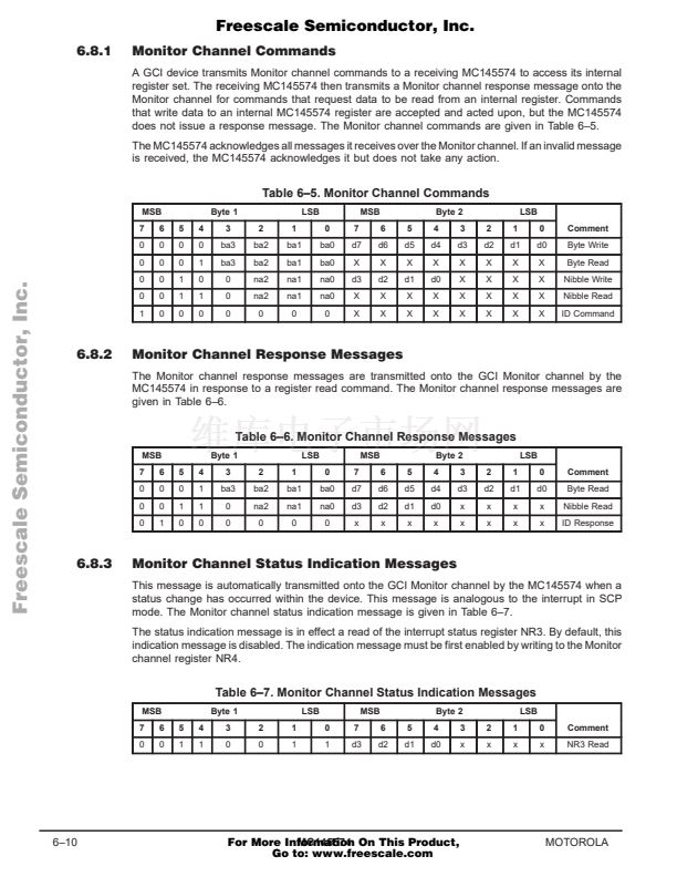
The MC145574 supports three basic types of Monitor channel messages. The first group of messages
are commands that read or write the internal register set of the MC145574. See Sections 8, 9, and
10 for the complete description of the MC145574 register set. The second group of messages are
responses from the MC145574. These responses are transmitted by the MC145574 after it receives
a register read or write command over the Monitor channel. The third type of Monitor channel message
is the Status Indication Message. When enabled, this message indicates a change in interrupt status
register NR3.
6鈥?
MC145574
For More Information On This Product,
Go to: www.freescale.com
MOTOROLA


 1
1
 2
2
 3
3
 4
4
 5
5
 6
6
 7
7
 8
8
 9
9
 10
10
 11
11
 12
12
 13
13
 14
14
 15
15
 16
16
 17
17
 18
18
 19
19
 20
20
 21
21
 22
22
 23
23
 24
24
 25
25
 26
26
 27
27
 28
28
 29
29
 30
30
 31
31
 32
32
 33
33
 34
34
 35
35
 36
36
 37
37
 38
38
 39
39
 40
40
 41
41
 42
42
 43
43
 44
44
 45
45
 46
46
 47
47
 48
48
 49
49
 50
50
 51
51
 52
52
 53
53
 54
54
 55
55
 56
56
 57
57
 58
58
 59
59
 60
60
 61
61
 62
62
 63
63
 64
64
 65
65
 66
66
 67
67
 68
68
 69
69
 70
70
 71
71
 72
72
 73
73
 74
74
 75
75
 76
76
 77
77
 78
78
 79
79
 80
80
 81
81
 82
82
 83
83
 84
84
 85
85
 86
86
 87
87
 88
88
 89
89
 90
90
 91
91
 92
92
 93
93
 94
94
 95
95
 96
96
 97
97
 98
98
 99
99
 100
100
 101
101
 102
102
 103
103
 104
104
 105
105
 106
106
 107
107
 108
108
 109
109
 110
110
 111
111
 112
112
 113
113
 114
114
 115
115
 116
116
 117
117
 118
118
 119
119
 120
120
 121
121
 122
122
 123
123
 124
124
 125
125
 126
126
 127
127
 128
128
 129
129
 130
130
 131
131
 132
132
 133
133
 134
134
 135
135
 136
136
 137
137
 138
138
 139
139
 140
140
 141
141
 142
142
 143
143
 144
144
 145
145
 146
146
 147
147
 148
148
 149
149
 150
150
 151
151
 152
152
 153
153
 154
154
 155
155
 156
156
 157
157
 158
158
 159
159
 160
160
 161
161
 162
162
 163
163
 164
164
