鈮?/div>
1024 * (C
INS
鈥?C
INN
).
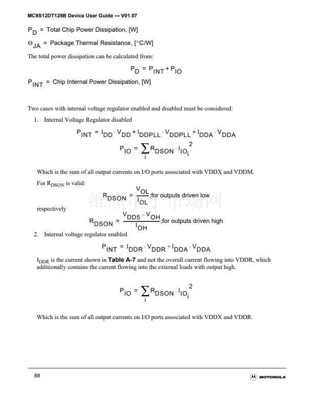
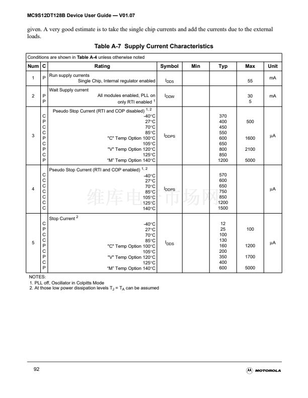
A.2.2.3 Current injection
There are two cases to consider.
1. A current is injected into the channel being converted. The channel being stressed has conversion
values of $3FF ($FF in 8-bit mode) for analog inputs greater than V
RH
and $000 for values less than
V
RL
unless the current is higher than specified as disruptive conditions.
2. Current is injected into pins in the neighborhood of the channel being converted. A portion of this
current is picked up by the channel (coupling ratio K), This additional current impacts the accuracy
of the conversion depending on the source resistance.
The additional input voltage error on the converted channel can be calculated as V
ERR
= K * R
S
*
I
INJ
, with I
INJ
being the sum of the currents injected into the two pins adjacent to the converted
channe
Table A-9 ATD Electrical Characteristics
Conditions are shown in
Table A-4
unless otherwise noted
Num C
1
2
3
4
5
Rating
Symbol
R
S
C
INN
C
INS
I
NA
K
p
K
n
Min
-
Typ
-
Max
1
10
22
Unit
K鈩?/div>
pF
mA
A/A
A/A
C Max input Source Resistance
Total Input Capacitance
T Non Sampling
Sampling
C Disruptive Analog Input Current
C Coupling Ratio positive current injection
C Coupling Ratio negative current injection
-2.5
2.5
10
-4
10
-2
94


 1
1
 2
2
 3
3
 4
4
 5
5
 6
6
 7
7
 8
8
 9
9
 10
10
 11
11
 12
12
 13
13
 14
14
 15
15
 16
16
 17
17
 18
18
 19
19
 20
20
 21
21
 22
22
 23
23
 24
24
 25
25
 26
26
 27
27
 28
28
 29
29
 30
30
 31
31
 32
32
 33
33
 34
34
 35
35
 36
36
 37
37
 38
38
 39
39
 40
40
 41
41
 42
42
 43
43
 44
44
 45
45
 46
46
 47
47
 48
48
 49
49
 50
50
 51
51
 52
52
 53
53
 54
54
 55
55
 56
56
 57
57
 58
58
 59
59
 60
60
 61
61
 62
62
 63
63
 64
64
 65
65
 66
66
 67
67
 68
68
 69
69
 70
70
 71
71
 72
72
 73
73
 74
74
 75
75
 76
76
 77
77
 78
78
 79
79
 80
80
 81
81
 82
82
 83
83
 84
84
 85
85
 86
86
 87
87
 88
88
 89
89
 90
90
 91
91
 92
92
 93
93
 94
94
 95
95
 96
96
 97
97
 98
98
 99
99
 100
100
 101
101
 102
102
 103
103
 104
104
 105
105
 106
106
 107
107
 108
108
 109
109
 110
110
 111
111
 112
112
 113
113
 114
114
 115
115
 116
116
 117
117
 118
118
 119
119
 120
120
 121
121
 122
122
 123
123
 124
124
