Philips Semiconductors
Preliminary specification
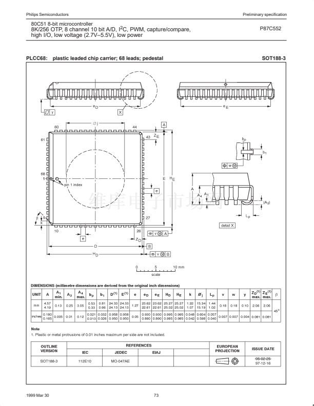
80C51 8-bit microcontroller
8K/256 OTP, 8 channel 10 bit A/D, I
2
C, PWM,
capture/compare, high I/O, low voltage (2.7V鈥?.5V), low power
P87C552
In a more complex system the following could be used to select
slaves 1 and 2 while excluding slave 0:
Slave 0
SADDR =
SADEN =
Given
=
SADDR =
SADEN =
Given
=
SADDR =
SADEN =
Given
=
1100 0000
1111 1001
1100 0XX0
1110 0000
1111 1010
1110 0X0X
1110 0000
1111 1100
1110 00XX
Slave 1
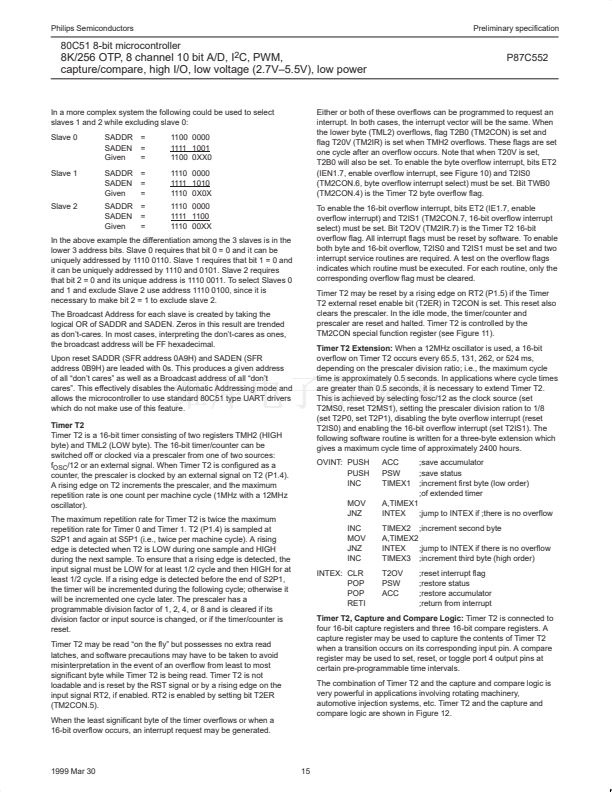
Either or both of these overflows can be programmed to request an
interrupt. In both cases, the interrupt vector will be the same. When
the lower byte (TML2) overflows, flag T2B0 (TM2CON) is set and
flag T20V (TM2IR) is set when TMH2 overflows. These flags are set
one cycle after an overflow occurs. Note that when T20V is set,
T2B0 will also be set. To enable the byte overflow interrupt, bits ET2
(IEN1.7, enable overflow interrupt, see Figure 10) and T2IS0
(TM2CON.6, byte overflow interrupt select) must be set. Bit TWB0
(TM2CON.4) is the Timer T2 byte overflow flag.
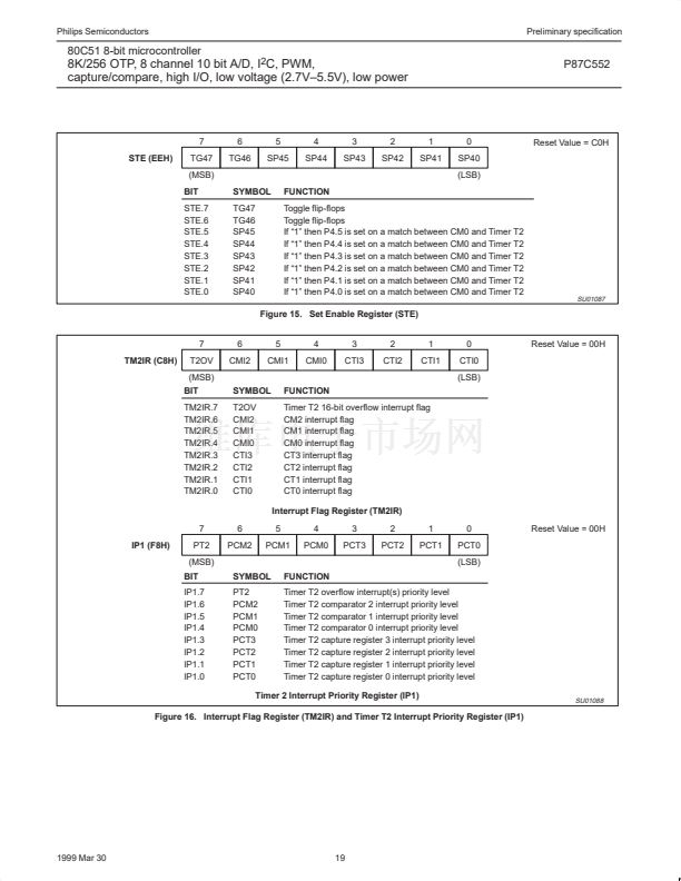
To enable the 16-bit overflow interrupt, bits ET2 (IE1.7, enable
overflow interrupt) and T2IS1 (TM2CON.7, 16-bit overflow interrupt
select) must be set. Bit T2OV (TM2IR.7) is the Timer T2 16-bit
overflow flag. All interrupt flags must be reset by software. To enable
both byte and 16-bit overflow, T2IS0 and T2IS1 must be set and two
interrupt service routines are required. A test on the overflow flags
indicates which routine must be executed. For each routine, only the
corresponding overflow flag must be cleared.
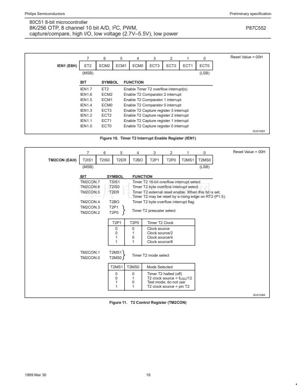
Timer T2 may be reset by a rising edge on RT2 (P1.5) if the Timer
T2 external reset enable bit (T2ER) in T2CON is set. This reset also
clears the prescaler. In the idle mode, the timer/counter and
prescaler are reset and halted. Timer T2 is controlled by the
TM2CON special function register (see Figure 11).
Timer T2 Extension:
When a 12MHz oscillator is used, a 16-bit
overflow on Timer T2 occurs every 65.5, 131, 262, or 524 ms,
depending on the prescaler division ratio; i.e., the maximum cycle
time is approximately 0.5 seconds. In applications where cycle times
are greater than 0.5 seconds, it is necessary to extend Timer T2.
This is achieved by selecting fosc/12 as the clock source (set
T2MS0, reset T2MS1), setting the prescaler division ration to 1/8
(set T2P0, set T2P1), disabling the byte overflow interrupt (reset
T2IS0) and enabling the 16-bit overflow interrupt (set T2IS1). The
following software routine is written for a three-byte extension which
gives a maximum cycle time of approximately 2400 hours.
OVINT: PUSH
PUSH
INC
MOV
JNZ
INC
MOV
JNZ
INC
INTEX: CLR
POP
POP
RETI
ACC
PSW
TIMEX1
;save accumulator
;save status
;increment first byte (low order)
;of extended timer
Slave 2
In the above example the differentiation among the 3 slaves is in the
lower 3 address bits. Slave 0 requires that bit 0 = 0 and it can be
uniquely addressed by 1110 0110. Slave 1 requires that bit 1 = 0 and
it can be uniquely addressed by 1110 and 0101. Slave 2 requires
that bit 2 = 0 and its unique address is 1110 0011. To select Slaves 0
and 1 and exclude Slave 2 use address 1110 0100, since it is
necessary to make bit 2 = 1 to exclude slave 2.
The Broadcast Address for each slave is created by taking the
logical OR of SADDR and SADEN. Zeros in this result are trended
as don鈥檛-cares. In most cases, interpreting the don鈥檛-cares as ones,
the broadcast address will be FF hexadecimal.
Upon reset SADDR (SFR address 0A9H) and SADEN (SFR
address 0B9H) are leaded with 0s. This produces a given address
of all 鈥渄on鈥檛 cares鈥?as well as a Broadcast address of all 鈥渄on鈥檛
cares鈥? This effectively disables the Automatic Addressing mode and
allows the microcontroller to use standard 80C51 type UART drivers
which do not make use of this feature.
Timer T2
Timer T2 is a 16-bit timer consisting of two registers TMH2 (HIGH
byte) and TML2 (LOW byte). The 16-bit timer/counter can be
switched off or clocked via a prescaler from one of two sources:
f
OSC
/12 or an external signal. When Timer T2 is configured as a
counter, the prescaler is clocked by an external signal on T2 (P1.4).
A rising edge on T2 increments the prescaler, and the maximum
repetition rate is one count per machine cycle (1MHz with a 12MHz
oscillator).
The maximum repetition rate for Timer T2 is twice the maximum
repetition rate for Timer 0 and Timer 1. T2 (P1.4) is sampled at
S2P1 and again at S5P1 (i.e., twice per machine cycle). A rising
edge is detected when T2 is LOW during one sample and HIGH
during the next sample. To ensure that a rising edge is detected, the
input signal must be LOW for at least 1/2 cycle and then HIGH for at
least 1/2 cycle. If a rising edge is detected before the end of S2P1,
the timer will be incremented during the following cycle; otherwise it
will be incremented one cycle later. The prescaler has a
programmable division factor of 1, 2, 4, or 8 and is cleared if its
division factor or input source is changed, or if the timer/counter is
reset.
Timer T2 may be read 鈥渙n the fly鈥?but possesses no extra read
latches, and software precautions may have to be taken to avoid
misinterpretation in the event of an overflow from least to most
significant byte while Timer T2 is being read. Timer T2 is not
loadable and is reset by the RST signal or by a rising edge on the
input signal RT2, if enabled. RT2 is enabled by setting bit T2ER
(TM2CON.5).
When the least significant byte of the timer overflows or when a
16-bit overflow occurs, an interrupt request may be generated.
A,TIMEX1
INTEX
;jump to INTEX if ;there is no overflow
TIMEX2 ;increment second byte
A,TIMEX2
INTEX
;jump to INTEX if there is no overflow
TIMEX3 ;increment third byte (high order)
T2OV
PSW
ACC
;reset interrupt flag
;restore status
;restore accumulator
;return from interrupt
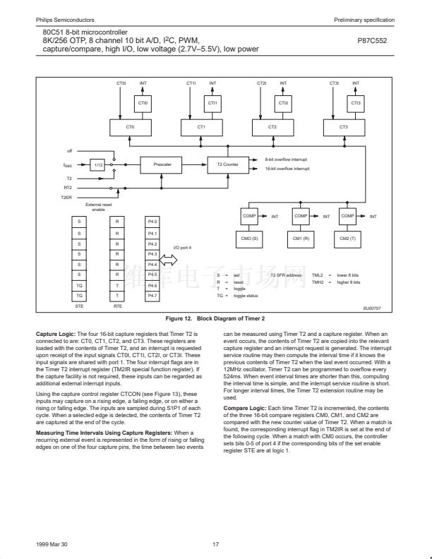
Timer T2, Capture and Compare Logic:
Timer T2 is connected to
four 16-bit capture registers and three 16-bit compare registers. A
capture register may be used to capture the contents of Timer T2
when a transition occurs on its corresponding input pin. A compare
register may be used to set, reset, or toggle port 4 output pins at
certain pre-programmable time intervals.
The combination of Timer T2 and the capture and compare logic is
very powerful in applications involving rotating machinery,
automotive injection systems, etc. Timer T2 and the capture and
compare logic are shown in Figure 12.
1999 Mar 30
15


 1
1
 2
2
 3
3
 4
4
 5
5
 6
6
 7
7
 8
8
 9
9
 10
10
 11
11
 12
12
 13
13
 14
14
 15
15
 16
16
 17
17
 18
18
 19
19
 20
20
 21
21
 22
22
 23
23
 24
24
 25
25
 26
26
 27
27
 28
28
 29
29
 30
30
 31
31
 32
32
 33
33
 34
34
 35
35
 36
36
 37
37
 38
38
 39
39
 40
40
 41
41
 42
42
 43
43
 44
44
 45
45
 46
46
 47
47
 48
48
 49
49
 50
50
 51
51
 52
52
 53
53
 54
54
 55
55
 56
56
 57
57
 58
58
 59
59
 60
60
 61
61
 62
62
 63
63
 64
64
 65
65
 66
66
 67
67
 68
68
 69
69
 70
70
 71
71
 72
72
 73
73
 74
74
