Philips Semiconductors
Preliminary specification
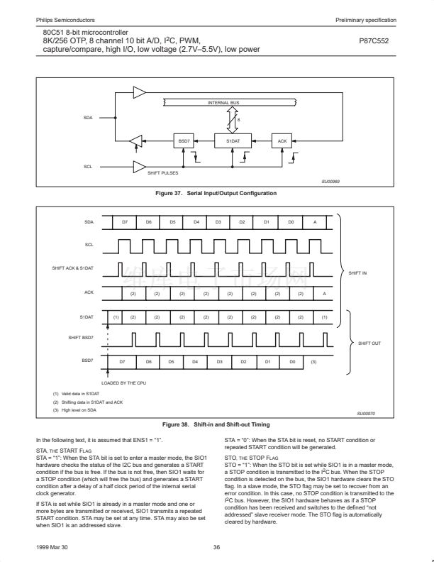
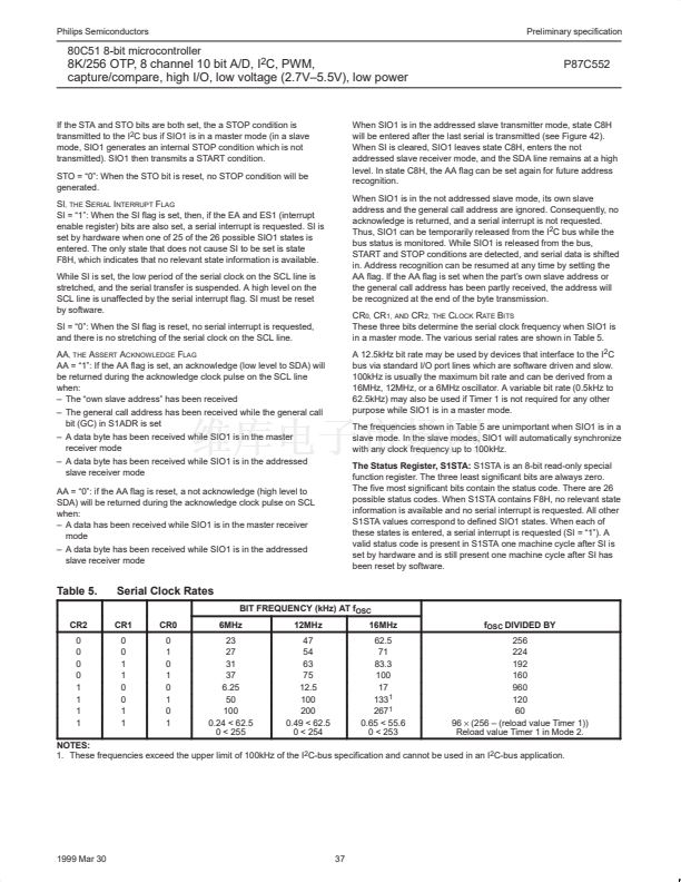
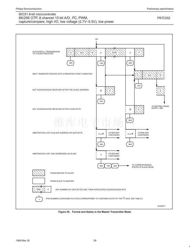
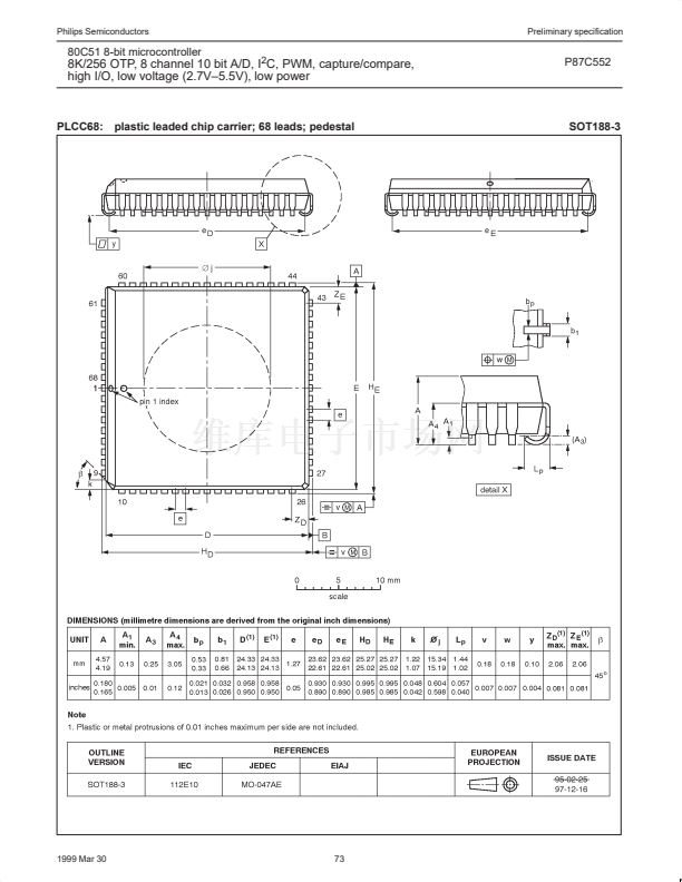
80C51 8-bit microcontroller
8K/256 OTP, 8 channel 10 bit A/D, I
2
C, PWM,
capture/compare, high I/O, low voltage (2.7V鈥?.5V), low power
P87C552
CT0I
INT
CT1I
INT
CT2I
INT
CT3I
INT
CTI0
CTI1
CTI2
CTI3
CT0
CT1
CT2
CT3
off
8-bit overflow interrupt
f
osc
T2
RT2
T2ER
External reset
enable
COMP
S
S
S
S
S
S
TG
TG
STE
R
R
R
R
R
R
T
T
RTE
P4.0
P4.1
CMO (S)
P4.2
P4.3
P4.4
P4.5
P4.6
P4.7
S
R
T
=
=
=
set
reset
toggle
toggle status
T2 SFR address:
TML2
TMH2
=
=
lower 8 bits
higher 8 bits
I/O port 4
CM1 (R)
CM2 (T)
INT
COMP
INT
COMP
INT
1/12
Prescaler
T2 Counter
16-bit overflow interrupt
TG =
SU00757
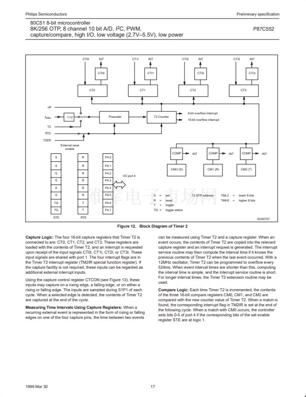
Figure 12. Block Diagram of Timer 2
Capture Logic:
The four 16-bit capture registers that Timer T2 is
connected to are: CT0, CT1, CT2, and CT3. These registers are
loaded with the contents of Timer T2, and an interrupt is requested
upon receipt of the input signals CT0I, CT1I, CT2I, or CT3I. These
input signals are shared with port 1. The four interrupt flags are in
the Timer T2 interrupt register (TM2IR special function register). If
the capture facility is not required, these inputs can be regarded as
additional external interrupt inputs.
Using the capture control register CTCON (see Figure 13), these
inputs may capture on a rising edge, a falling edge, or on either a
rising or falling edge. The inputs are sampled during S1P1 of each
cycle. When a selected edge is detected, the contents of Timer T2
are captured at the end of the cycle.
Measuring Time Intervals Using Capture Registers:
When a
recurring external event is represented in the form of rising or falling
edges on one of the four capture pins, the time between two events
can be measured using Timer T2 and a capture register. When an
event occurs, the contents of Timer T2 are copied into the relevant
capture register and an interrupt request is generated. The interrupt
service routine may then compute the interval time if it knows the
previous contents of Timer T2 when the last event occurred. With a
12MHz oscillator, Timer T2 can be programmed to overflow every
524ms. When event interval times are shorter than this, computing
the interval time is simple, and the interrupt service routine is short.
For longer interval times, the Timer T2 extension routine may be
used.
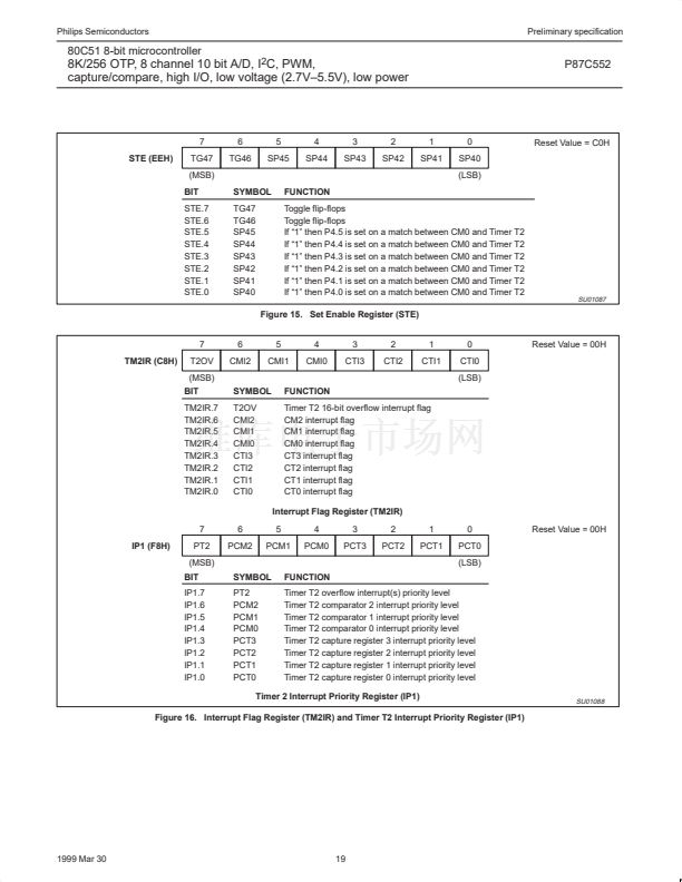
Compare Logic:
Each time Timer T2 is incremented, the contents
of the three 16-bit compare registers CM0, CM1, and CM2 are
compared with the new counter value of Timer T2. When a match is
found, the corresponding interrupt flag in TM2IR is set at the end of
the following cycle. When a match with CM0 occurs, the controller
sets bits 0-5 of port 4 if the corresponding bits of the set enable
register STE are at logic 1.
1999 Mar 30
17


 1
1
 2
2
 3
3
 4
4
 5
5
 6
6
 7
7
 8
8
 9
9
 10
10
 11
11
 12
12
 13
13
 14
14
 15
15
 16
16
 17
17
 18
18
 19
19
 20
20
 21
21
 22
22
 23
23
 24
24
 25
25
 26
26
 27
27
 28
28
 29
29
 30
30
 31
31
 32
32
 33
33
 34
34
 35
35
 36
36
 37
37
 38
38
 39
39
 40
40
 41
41
 42
42
 43
43
 44
44
 45
45
 46
46
 47
47
 48
48
 49
49
 50
50
 51
51
 52
52
 53
53
 54
54
 55
55
 56
56
 57
57
 58
58
 59
59
 60
60
 61
61
 62
62
 63
63
 64
64
 65
65
 66
66
 67
67
 68
68
 69
69
 70
70
 71
71
 72
72
 73
73
 74
74
