Philips Semiconductors
Preliminary specification
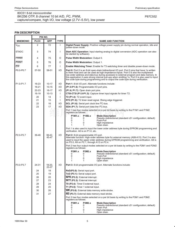
80C51 8-bit microcontroller
8K/256 OTP, 8 channel 10 bit A/D, I
2
C, PWM,
capture/compare, high I/O, low voltage (2.7V鈥?.5V), low power
P87C552
SIO1, I
2
C Serial I/O:
The I
2
C bus uses two wires (SDA and SCL) to
transfer information between devices connected to the bus. The
main features of the bus are:
鈥?Bidirectional data transfer between masters and slaves
鈥?Multimaster bus (no central master)
鈥?Arbitration between simultaneously transmitting masters without
corruption of serial data on the bus
鈥?Serial clock synchronization allows devices with different bit rates
to communicate via one serial bus
鈥?Serial clock synchronization can be used as a handshake
mechanism to suspend and resume serial transfer
鈥?The I
2
C bus may be used for test and diagnostic purposes
The output latches of P1.6 and P1.7 must be set to logic 1 in order
to enable SIO1.
The 8XC552 on-chip
logic provides a serial interface that meets
the I
2
C bus specification and supports all transfer modes (other than
the low-speed mode) from and to the I
2
C bus. The SIO1 logic
handles bytes transfer autonomously. It also keeps track of serial
transfers, and a status register (S1STA) reflects the status of SIO1
and the I
2
C bus.
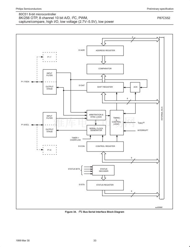
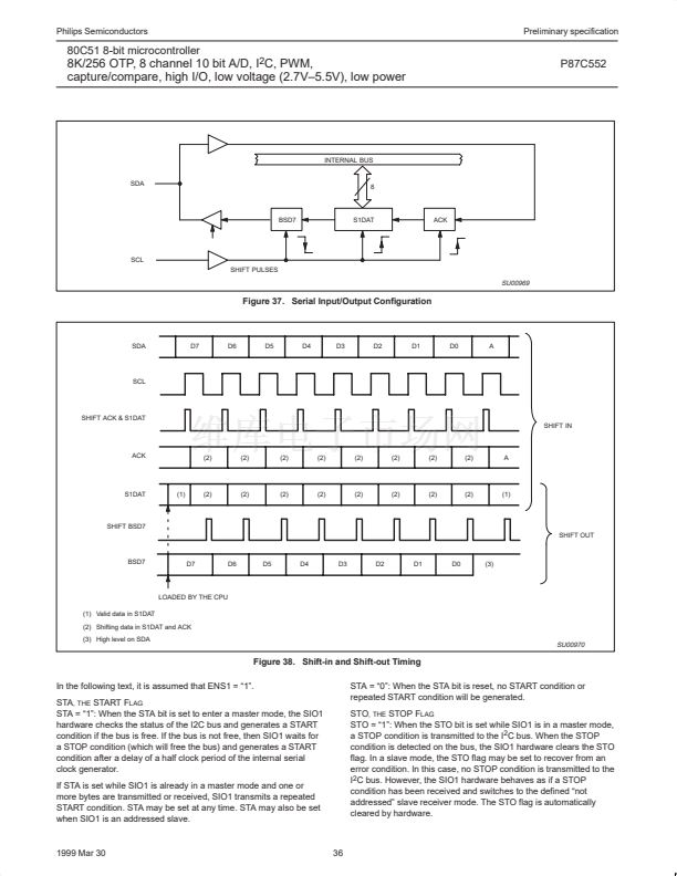
The CPU interfaces to the I
2
C logic via the following four special
function registers: S1CON (SIO1 control register), S1STA (SIO1
status register), S1DAT (SIO1 data register), and S1ADR (SIO1
slave address register). The SIO1 logic interfaces to the external I
2
C
bus via two port 1 pins: P1.6/SCL (serial clock line) and P1.7/SDA
(serial data line).
A typical I
2
C bus configuration is shown in Figure 32, and Figure 33
shows how a data transfer is accomplished on the bus. Depending
on the state of the direction bit (R/W), two types of data transfers are
possible on the I
2
C bus:
1. Data transfer from a master transmitter to a slave receiver. The
first byte transmitted by the master is the slave address. Next
follows a number of data bytes. The slave returns an
acknowledge bit after each received byte.
2. Data transfer from a slave transmitter to a master receiver. The
first byte (the slave address) is transmitted by the master. The
slave then returns an acknowledge bit. Next follows the data
bytes transmitted by the slave to the master. The master returns
an acknowledge bit after all received bytes other than the last
byte. At the end of the last received byte, a 鈥渘ot acknowledge鈥?is
returned.
The master device generates all of the serial clock pulses and the
START and STOP conditions. A transfer is ended with a STOP
condition or with a repeated START condition. Since a repeated
START condition is also the beginning of the next serial transfer, the
I
2
C bus will not be released.
I
2
C
Modes of Operation:
The on-chip SIO1 logic may operate in the
following four modes:
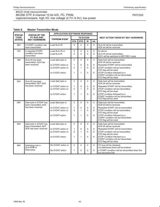
1. Master Transmitter Mode:
Serial data output through P1.7/SDA while P1.6/SCL outputs the
serial clock. The first byte transmitted contains the slave address
of the receiving device (7 bits) and the data direction bit. In this
case the data direction bit (R/W) will be logic 0, and we say that
a 鈥淲鈥?is transmitted. Thus the first byte transmitted is SLA+W.
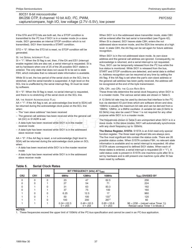
Serial data is transmitted 8 bits at a time. After each byte is
transmitted, an acknowledge bit is received. START and STOP
conditions are output to indicate the beginning and the end of a
serial transfer.
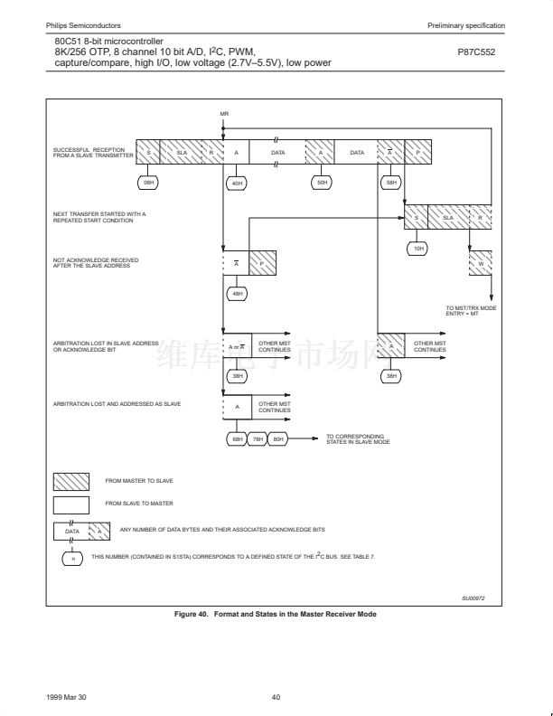
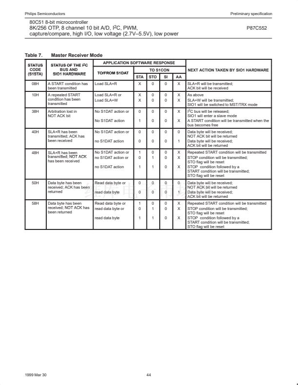
2. Master Receiver Mode:
The first byte transmitted contains the slave address of the
transmitting device (7 bits) and the data direction bit. In this case
the data direction bit (R/W) will be logic 1, and we say that an 鈥淩鈥?/div>
is transmitted. Thus the first byte transmitted is SLA+R. Serial
data is received via P1.7/SDA while P1.6/SCL outputs the serial
clock. Serial data is received 8 bits at a time. After each byte is
received, an acknowledge bit is transmitted. START and STOP
conditions are output to indicate the beginning and end of a
serial transfer.
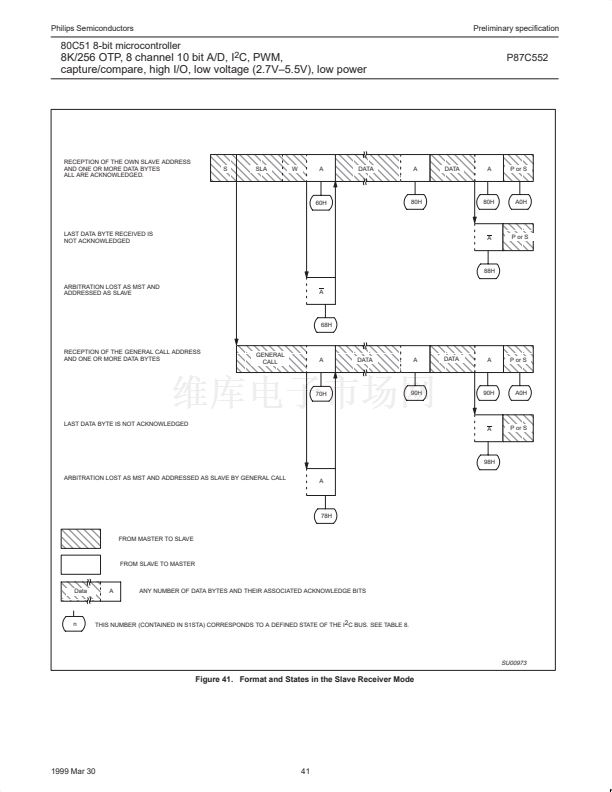
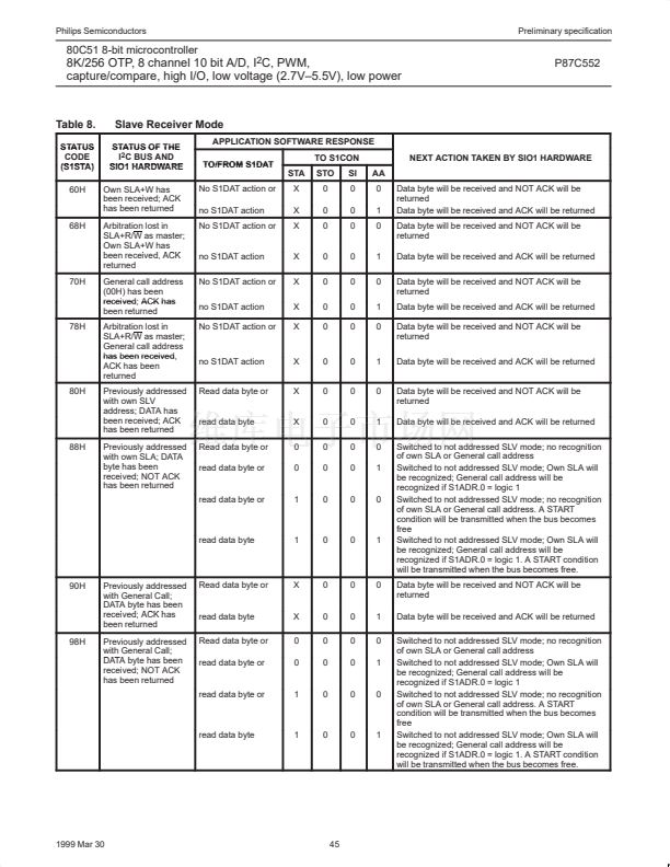
3. Slave Receiver Mode:
Serial data and the serial clock are received through P1.7/SDA
and P1.6/SCL. After each byte is received, an acknowledge bit is
transmitted. START and STOP conditions are recognized as the
beginning and end of a serial transfer. Address recognition is
performed by hardware after reception of the slave address and
direction bit.
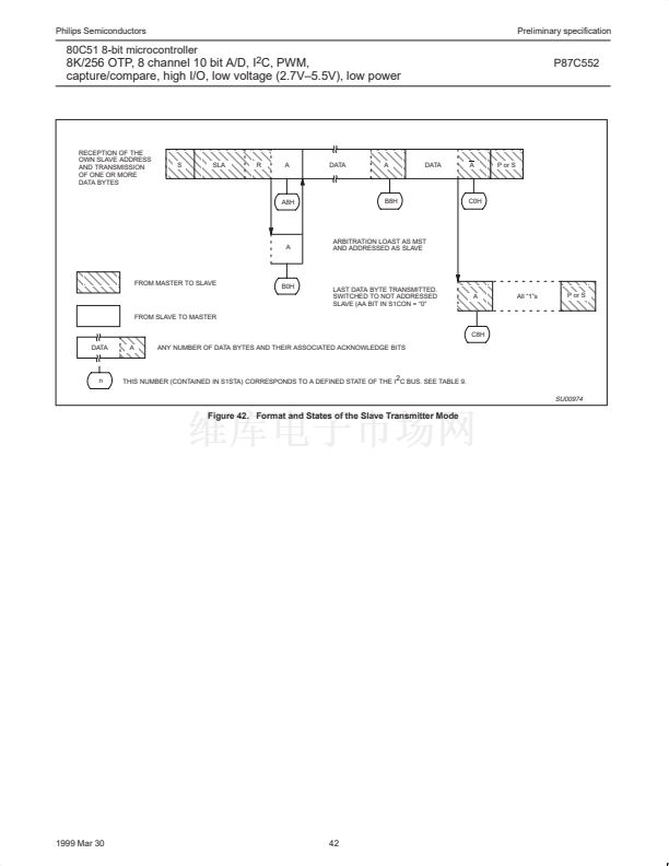
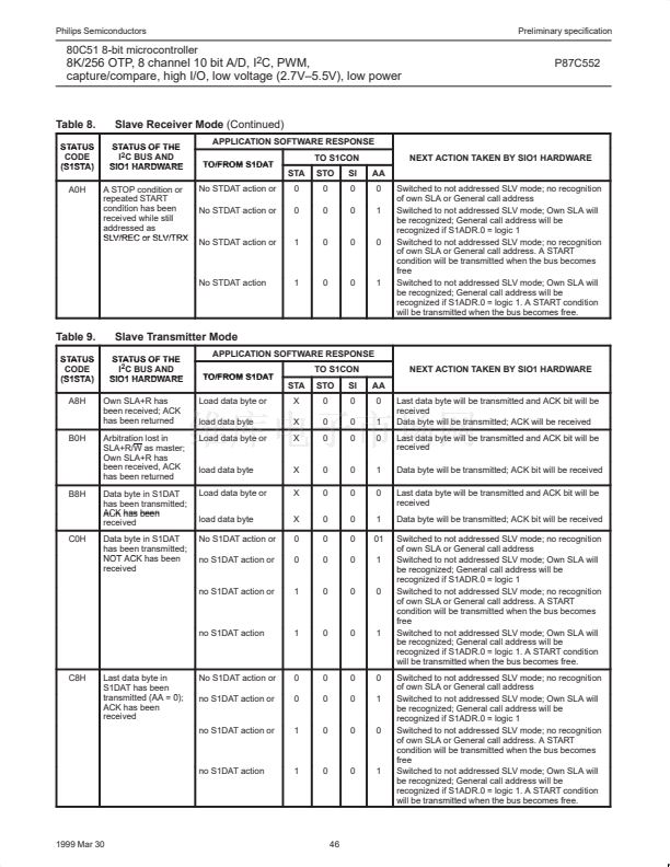
4. Slave Transmitter Mode:
The first byte is received and handled as in the slave receiver
mode. However, in this mode, the direction bit will indicate that
the transfer direction is reversed. Serial data is transmitted via
P1.7/SDA while the serial clock is input through P1.6/SCL.
START and STOP conditions are recognized as the beginning
and end of a serial transfer.
In a given application, SIO1 may operate as a master and as a
slave. In the slave mode, the SIO1 hardware looks for its own slave
address and the general call address. If one of these addresses is
detected, an interrupt is requested. When the microcontroller wishes
to become the bus master, the hardware waits until the bus is free
before the master mode is entered so that a possible slave action is
not interrupted. If bus arbitration is lost in the master mode, SIO1
switches to the slave mode immediately and can detect its own
slave address in the same serial transfer.
1999 Mar 30
31


 1
1
 2
2
 3
3
 4
4
 5
5
 6
6
 7
7
 8
8
 9
9
 10
10
 11
11
 12
12
 13
13
 14
14
 15
15
 16
16
 17
17
 18
18
 19
19
 20
20
 21
21
 22
22
 23
23
 24
24
 25
25
 26
26
 27
27
 28
28
 29
29
 30
30
 31
31
 32
32
 33
33
 34
34
 35
35
 36
36
 37
37
 38
38
 39
39
 40
40
 41
41
 42
42
 43
43
 44
44
 45
45
 46
46
 47
47
 48
48
 49
49
 50
50
 51
51
 52
52
 53
53
 54
54
 55
55
 56
56
 57
57
 58
58
 59
59
 60
60
 61
61
 62
62
 63
63
 64
64
 65
65
 66
66
 67
67
 68
68
 69
69
 70
70
 71
71
 72
72
 73
73
 74
74
