HCC/HCF4054B/55B/56B
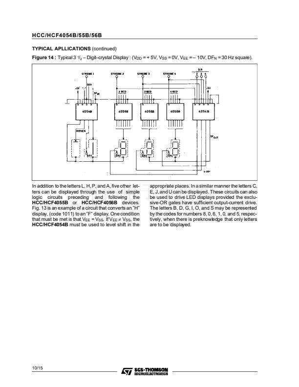
TYPICAL APPLICATIONS
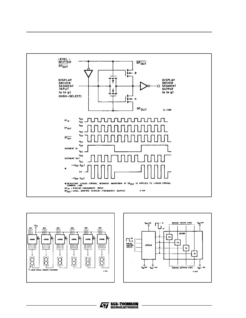
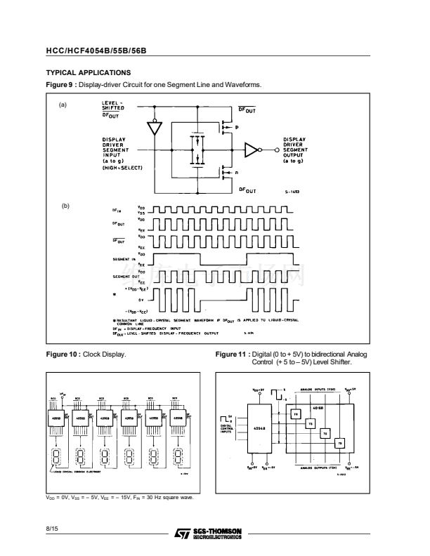
Figure 9 :
Display-driver Circuit for one Segment Line and Waveforms.
(a)
(b)
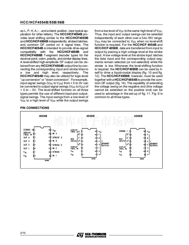
Figure 10 :
Clock Display.
Figure 11 :
Digital (0 to + 5V) to bidirectional Analog
Control (+ 5 to 鈥?5V) Level Shifter.
V
DD
= 0V, V
SS
= 鈥?5V, V
EE
= 鈥?15V, F
IN
= 30 Hz square wave.
8/15


 1
1
 2
2
 3
3
 4
4
 5
5
 6
6
 7
7
 8
8
 9
9
 10
10
 11
11
 12
12
 13
13
 14
14
 15
15