IDT77301
UtopiaFIFO鈩?1 to 4 (128 x 9 x 4) Demultiplexer-FIFO
Commercial and Industrial Temperature Ranges
Cell Size Programming
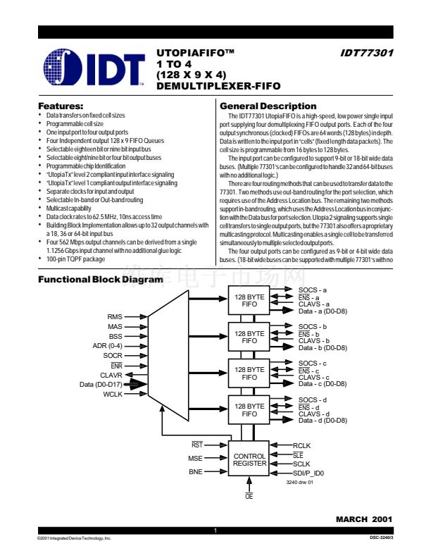
Data is transferred in 鈥渃ells鈥? for ATM, cell size is 53/54 bytes on an 8/
16-bit bus. The UtopiaFIFO can be programmed through the cell size
selection registers to any number of bytes between 16 and 128. Program-
ing is accomplished through a serial load port when the BSS is low ( 18
bit input data bus ) and parallel loading when BSS is high ( 9 bit input data
bus ) using the spare input data pins.
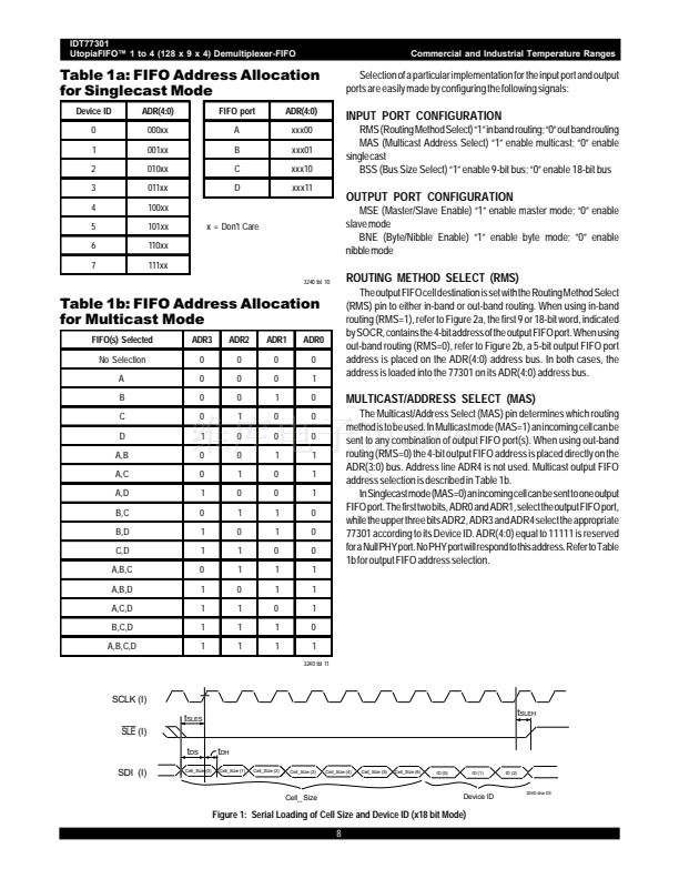
Use the Serial Load Enable (SLE), Serial Clock (SCLK) and the Serial
Data Load (SDI) pins to serially program the cell size and the device ID.
After Reset the ten bits are loaded to program the cell size and device ID.
The first seven bits program the cell size, with the first bit being the LSB.
The last three bits program the device ID, with the first of these three bits
being the LSB. For a cell size of 128 bytes set all seven cell size bits to zero.
You must set all ten bits when programing this register, even though the
singlecast mode does not require a device ID. The device ID is the PHY
port group as defined in the Utopia level 2 version 1 document. Refer to
Figure 1 for cell size timing diagram.
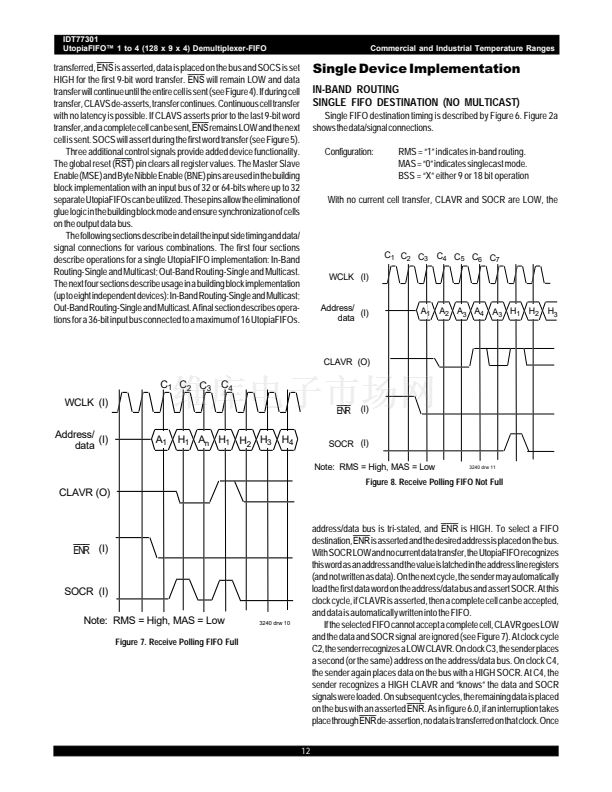
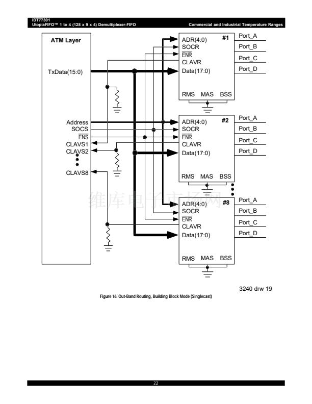
SOCR to mark the beginning of the cell. Data transfer continues until the
cell transfer is completed. When the cell size is reached, further writes are
blocked until new
ENR
and SOCR signals are received and a complete
cell can be accepted. The particular FIFO receiving data is selected by the
ADR0-4 lines; if available memory to store a complete cell exists, the
CLAVR signal is asserted.
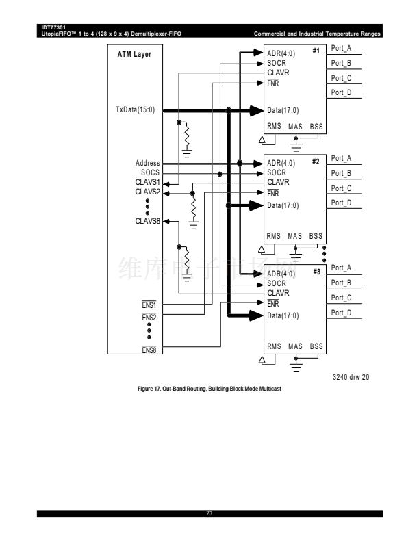
In multicast mode, cell transfer will occur only when all chosen FIFO
destinations have space for a complete cell. If any destination cannot take
a cell, the UtopiaFIFO will set CLAVR LOW. Once all destinations are
available, CLAVR will be asserted.
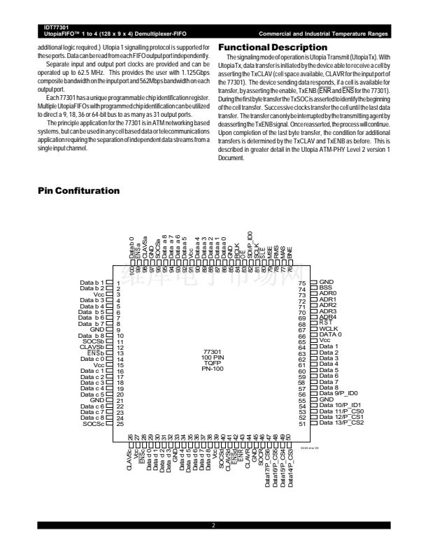
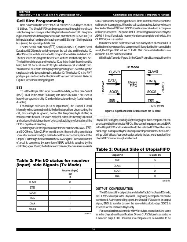
With UtopiaTx mode (Figure 3), the CLAVR signal is an output from the
Tx Mode
CLAVR
DATA
SOCR
Tx Mode
Utopia
FIFO
CLAVS
DATA
SOCS
BSS
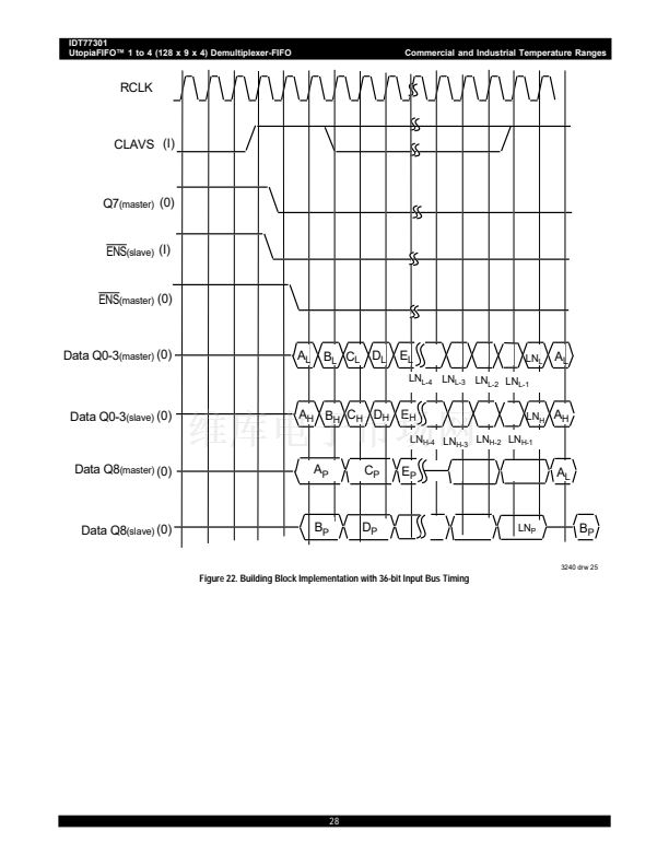
To set the Utopia FIFO input bus width to 9-bits, set Bus Size Select
(BSS) HIGH. In this mode SDI along with inputs D9 to D17, are used to
hardwire program the chip ID and cell size values directly (serial loading
disabled).
For odd byte cell sizes (in 18-bit input mode), the UtopiaFIFO will
internally write a dummy byte into the last byte position. Upon reading the
cell, this last byte is ignored; hence, this temporary byte stuffing is
transparent to the user. This does however, add to the memory utilization
and reduces the total number of bytes available by one for each cell the
FIFO is capable of handling.
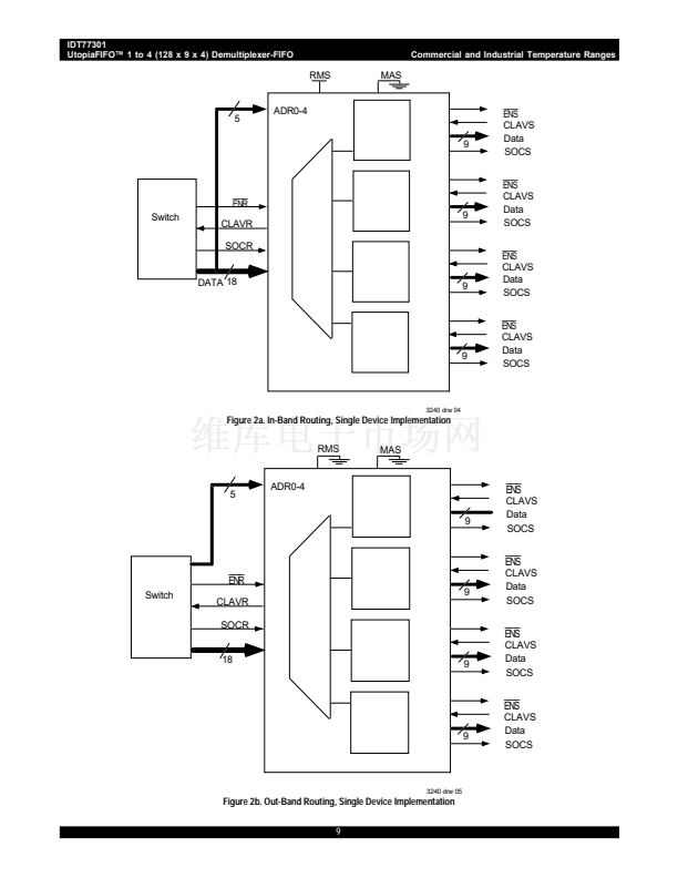
Control signals for the input data transfer side consists of CLAVR,
ENR,
and SOCR (see Table 2). Prior to cell transfer, the controlling agent (data
source for transmit mode) is notified a cell transfer can take place to the
UtopiaFIFO through the assertion of the CLAVR signal. Each word transfer
of a cell is completed by assertion of
ENR,
which is supplied by the
controlling agent. During the first data word transfer, the data source asserts
ENR
ENS
3240 drw 06
Figure 3. Signal and Data I/O Directions for Tx Mode
UtopiaFIFO telling the sending (controlling) agent that a complete cell can
be accepted by the selected FIFOs. The controlling agent asserts
ENR
to the UtopiaFIFO and data is written to the selected FIFO on the same
clock edge. As required by the Utopia protocol specifications, the CLAVR
will go LOW at least four clock cycles prior to the last word transfer if the
UtopiaFIFO cannot accept another cell.
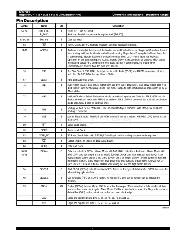
Table 3: Output Side of Utopia.I.O
Output Pin
Tx Mode I/O
O
I
O
O
3240 tbl 13
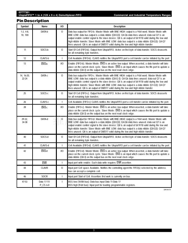
Table 2: Pin I/O status for receiver
(input) side Signals (Tx Mode)
Receiver (Input)
I/O
TX
CLAVR
O
I
I
I
I
I
3240 tbl 12
ENR
CLAVS
SOCR
Data
ENR
SOCR
Data
Clock
ADR0-4
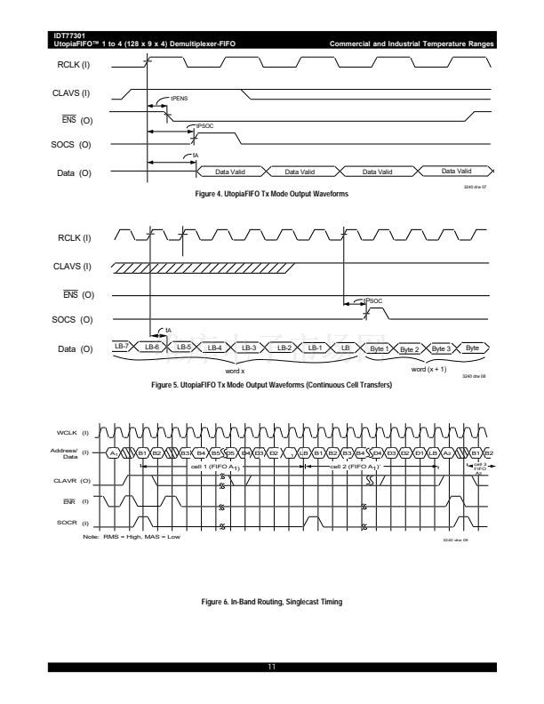
OUTPUT CONFIGURATION
The I/O status of the output pins are listed in Table 3. In UtopiaTX mode,
the CLAVS is an input to the UtopiaFIFO signaling a complete cell can be
transferred. As the controlling agent, the UtopiaFIFO asserts an output
signal,
ENS,
to transfer data on the same rising clock edge. SOCS is
asserted for the first output byte only.
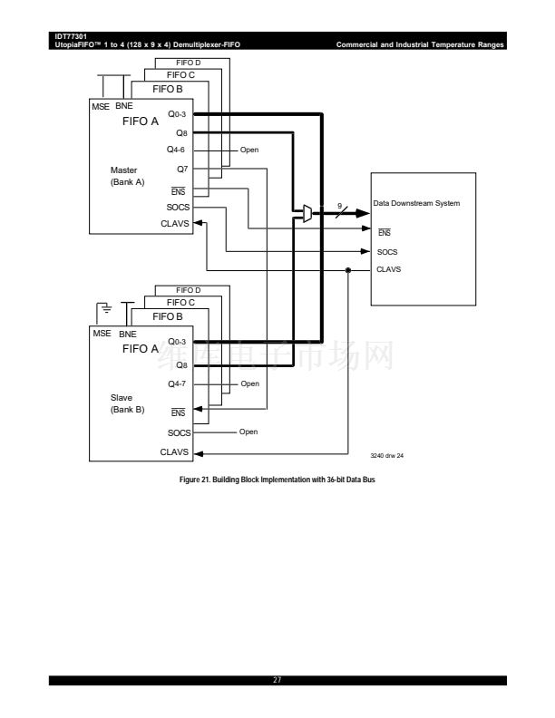
For operation in master mode with 9-bit output, operation is the same
as in the Utopia Level I specification. Once a CLAVS signal is asserted to
a selected output FIFO location, if a complete cell is available to be
10


 1
1
 2
2
 3
3
 4
4
 5
5
 6
6
 7
7
 8
8
 9
9
 10
10
 11
11
 12
12
 13
13
 14
14
 15
15
 16
16
 17
17
 18
18
 19
19
 20
20
 21
21
 22
22
 23
23
 24
24
 25
25
 26
26
 27
27
 28
28
 29
29
