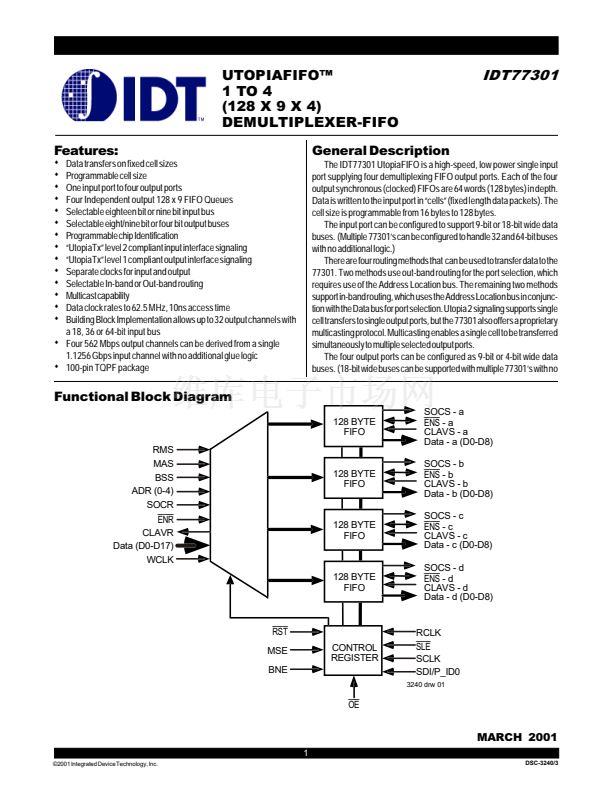
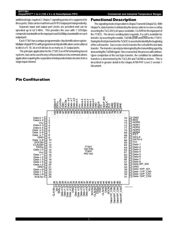
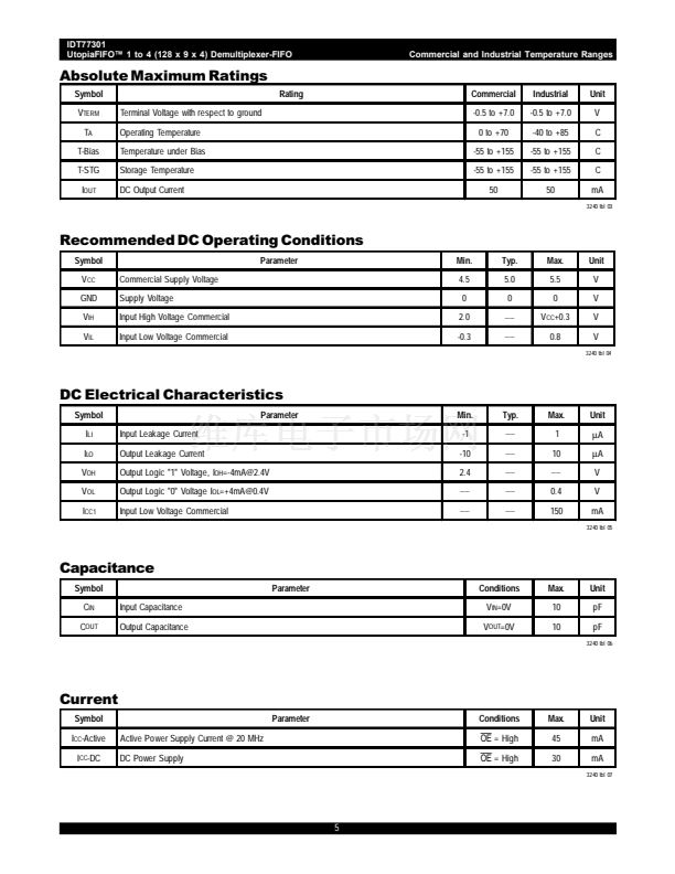
IDT77301
UtopiaFIFO鈩?1 to 4 (128 x 9 x 4) Demultiplexer-FIFO
Commercial and Industrial Temperature Ranges
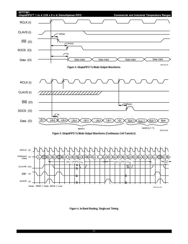
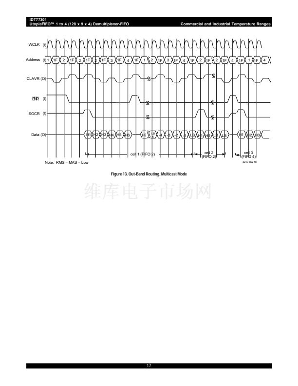
the CLAVR is asserted. On the next clock cycle, SOCR goes HIGH to
indicate the start of the next cell. Changing FIFO destinations result in only
a one clock cycle delay.
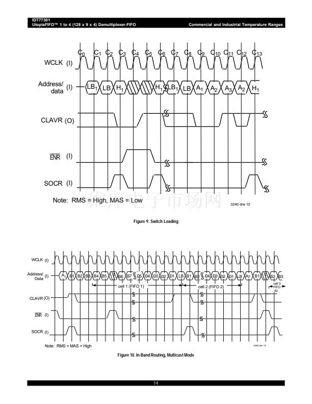
MULTICAST OPERATION
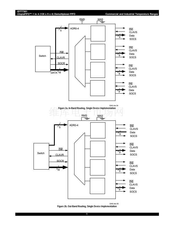
Configuration:
RMS = 鈥?鈥?indicates out-band routing.
MAS = 鈥?鈥?indicates multicast mode.
BSS = 鈥?鈥?18 bit operation
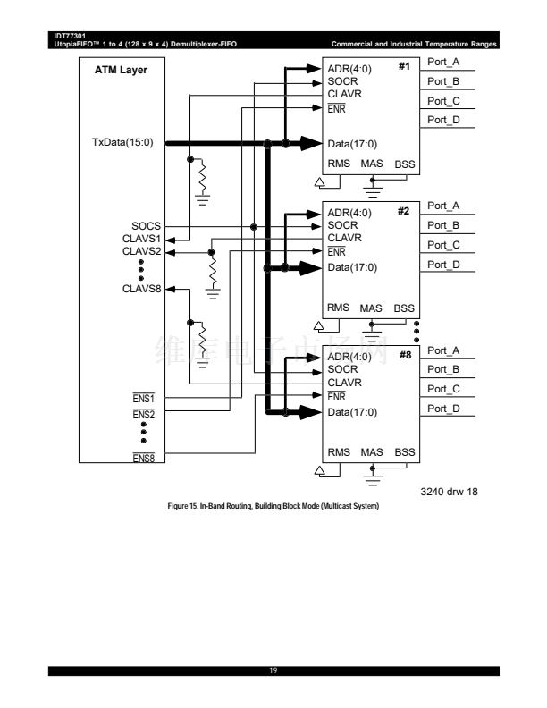
MULTICAST OPERATION
Configuration:
RMS = 鈥?鈥?indicates in-band routing.
MAS = 鈥?鈥?indicates multicast mode.
BSS = 鈥?鈥?18 bit operation
Operation in this mode is similar to single device mode. Data/signal
connections are shown in Figure 15 and timing is shown in Figure10. In
this implementation, these are separate
ENR
signals. With SOCR and
ENR
inactive and no current cell transfer, asserting
ENR
notifies each
device the current word is an address. For selected devices, those with
cell space available in all FIFOs have a HIGH CLAVR. If one or more
selected FIFOs in a given UtopiaFIFO do not have room, CLAVR is set
LOW.
As shown in Figure 10, and described above, continuous cell transfer
can occur with the same combination of FIFO destinations. With a change
in FIFO destinations, only a minimum of one cycle delay will occur.
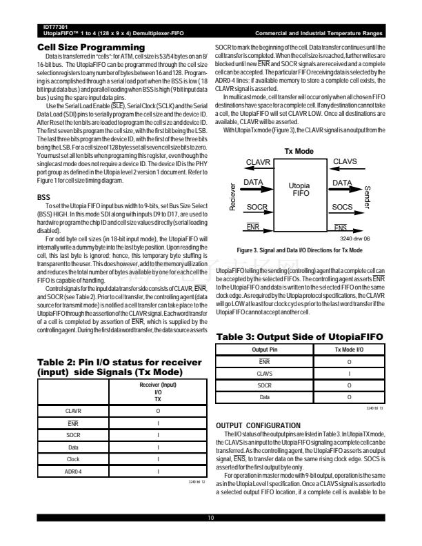
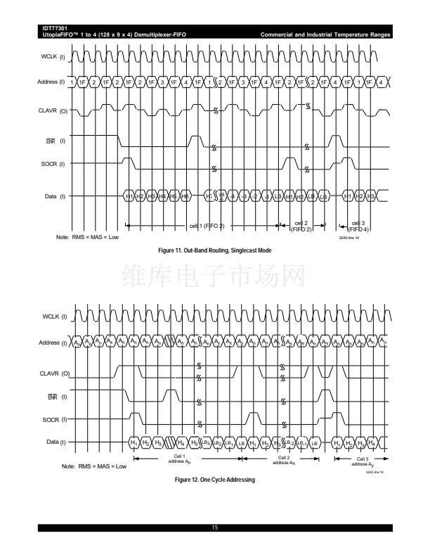
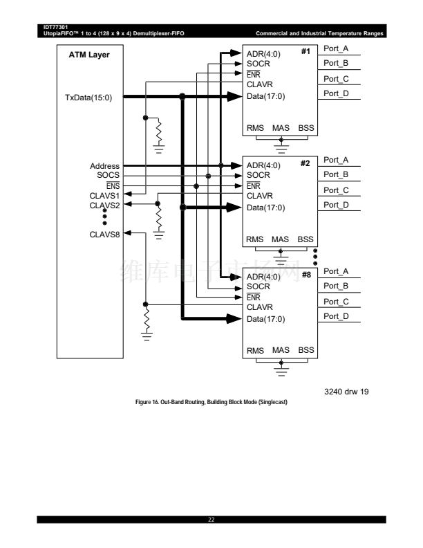
OUT-BAND ROUTING
SINGLE DEVICE DESTINATION (NO MULTICAST)
Configuration:
RMS = 鈥?鈥?indicates out-band routing.
MAS = 鈥?鈥?indicates no multicast mode.
BSS = 鈥?鈥?18 bit operation
To select from up to eight UtopiaFIFOs, connect address/data lines as
shown in Figure 16. There is one
ENR
and multiple CLAVR signals (one
per each UtopiaFIFO). The address bus is common to all UtopiaFIFOs.
The timing is the same as in Figure 11. Once the current cell transfer is
completed, a new
ENR
signal and address will switch data transfer to the
new destination. By changing destinations, there is a one cycle delay as
ENR
must be de-asserted to select the new location. The address is
loaded on a de-asserted
ENR
signal. If the selected device has space
for an entire cell, it asserts CLAVR HIGH. All non-selected devices CLAVR
signals are tri-stated. When the selected FIFO has a complete cell
available, the asserted CLAVR informs the upstream system it can send
data. On the next clock cycle,
ENR
asserts and data is placed on the data
bus and SOCR is asserted for the first word of data.
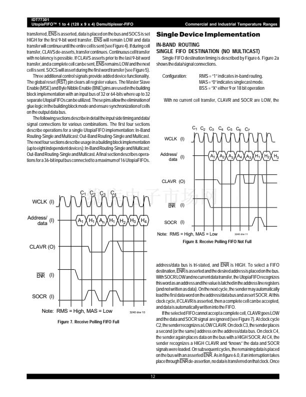
鈥淧olling鈥?of new address locations can occur during the current cell
transfer. However, only one Utopia FIFO device can be polled at a time
as the address bus is common to all devices. To 鈥減oll鈥?non-selected devices
will require separate
ENR
signals (one per Utopia FIFO) as well as
separate CLAVR lines to the switch.
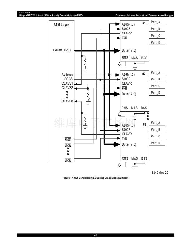
In this case any combination of the four output FIFOs can receive the
same cell and the combination can vary among the individual Utopia
devices. Figure 17 shows the data/address connections. In this mode
RMS and MAS are both set LOW. The timing is the same for the single
device implementation. Each UtopiaFIFO, in turn, has the FIFO multicast
destination(s) loaded in the address registers; the CLAVR signal is
evaluated for cell availability. Once all desired location CLAVR signals are
known and all locations are available, the switch can send data to all
UtopiaFIFOs. Data is transferred upon assertion of
ENR
(only to those
selected devices) and SOCR with the data on the address bus. At the end
of a given cell transfer, if the same set of destinations are used, continuous
transfer with no latency, can take place. For a new set of cell destinations,
there is a one cycle delay for each selected UtopiaFIFO; if for example,
four of the eight devices involve cell destinations, each device must be
programmed separately. A set of address enables are loaded into each
device on a asserted
ENR
value. Each device evaluates the availability
of the selected FIFO(s) and sends an appropriate CLAVR signal.
Polling of all UtopiaFIFOs (both selected and non-selected) during cell
transfer can take place. For those non-selected UtopiaFIFOs, a LOW
ENR
signal with a new address combination, with SOCR LOW will be
evaluated and CLAVR set accordingly. As a current cell transfer is taking
place, no new asserted SOCR (common to all devices) will occur. The
absence of a HIGH SOCR notifies the device not to load data. For the
currently selected UtopiaFIFOs, if the address is changed to poll a new
combination, the current cell
destination(s) will not be altered. If the next cell destination(s) are the
same as the current one, this polling address will not change these
destination(s); thus, continuous cell transfer can still occur despite the on-
going polling.
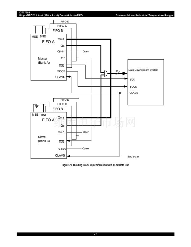
BUILDING BLOCK IMPLEMENTATION:
36-BIT INPUT BUS
Input data buses greater than 18-bits can be utilized with the UtopiaFIFO.
Figure 18 shows how to direct a 36-bit bus to multiple UtopiaFIFOs
(multicast mode). For each of the UtopiaFIFO destinations, two devices are
used. The 36-bit bus is split up into 8 4-bit streams plus parity bits. As shown
in Figure 20, the data bits D0-D3 remain in these positions. Data bits D4-
D7 become D18-21, parity bit D8 remains in D8, etc. The 鈥渘ew鈥?bits D0-
D17 are directed to the UtopiaFIFO 鈥淏ank A鈥?which is set as a master. The
鈥渘ew鈥?bits D18-D35 are directed to the UtopiaFIFO 鈥淏ank B鈥?which is set
as a slave. This rearranging of data assures that upon reading of the output
20


 1
1
 2
2
 3
3
 4
4
 5
5
 6
6
 7
7
 8
8
 9
9
 10
10
 11
11
 12
12
 13
13
 14
14
 15
15
 16
16
 17
17
 18
18
 19
19
 20
20
 21
21
 22
22
 23
23
 24
24
 25
25
 26
26
 27
27
 28
28
 29
29
