Preliminary W77E516
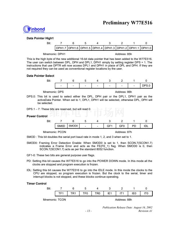
Data Pointer High1
Bit:
7
6
5
4
3
2
1
0
DPH1.7 DPH1.6 DPH1.5 DPH1.4 DPH1.3 DPH1.2 DPH1.1 DPH1.0
Mnemonic: DPH1
Address: 85h
This is the high byte of the new additional 16-bit data pointer that has been added to the W77E516.
The user can switch between DPL, DPH and DPL1, DPH1 simply by setting register DPS = 1. The
instructions that use DPTR will now access DPL1 and DPH1 in place of DPL and DPH. If they are
not required they can be used as conventional register locations by the user.
Data Pointer Select
Bit:
7
-
Mnemonic: DPS
6
-
5
-
4
-
3
-
2
-
Address: 86h
1
-
0
DPS.0
DPS.0: This bit is used to select either the DPL, DPH pair or the DPL1, DPH1 pair as the
activeData Pointer. When set to 1, DPL1, DPH1 will be selected, otherwise DPL, DPH will
be selected.
DPS.1
鈭?/div>
7: These bits are reserved, but will read 0.
Power Control
Bit:
7
SM0D
Mnemonic: PCON
6
SMOD0
5
-
4
-
3
GF1
2
GF0
Address: 87h
1
PD
0
IDL
SMOD : This bit doubles the serial port baud rate in mode 1, 2, and 3 when set to 1.
SMOD0: Framing Error Detection Enable: When SMOD0 is set to 1, then SCON.7(SCON1.7)
indicates a Frame Error and acts as the FE(FE_1) flag. When SMOD0 is 0, then
SCON.7(SCON1.7) acts as per the standard 8052 function.
GF1-0: These two bits are general purpose user flags.
PD: Setting this bit causes the W77E516 to go into the POWER DOWN mode. In this mode all the
clocks are stopped and program execution is frozen.
IDL: Setting this bit causes the W77E516 to go into the IDLE mode. In this mode the clocks to the
CPU are stopped, so program execution is frozen. But the clock to the serial, timer and
interrupt blocks is not stopped, and these blocks continue operating.
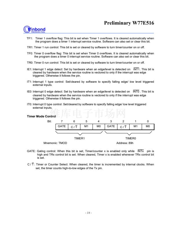
Timer Control
Bit:
7
TF1
Mnemonic: TCON
6
TR1
5
TF0
4
TR0
3
IE1
2
IT1
Address: 88h
Publication Release Date: August 16, 2002
Revision A1
1
IE0
0
IT0
- 13 -


 1
1
 2
2
 3
3
 4
4
 5
5
 6
6
 7
7
 8
8
 9
9
 10
10
 11
11
 12
12
 13
13
 14
14
 15
15
 16
16
 17
17
 18
18
 19
19
 20
20
 21
21
 22
22
 23
23
 24
24
 25
25
 26
26
 27
27
 28
28
 29
29
 30
30
 31
31
 32
32
 33
33
 34
34
 35
35
 36
36
 37
37
 38
38
 39
39
 40
40
 41
41
 42
42
 43
43
 44
44
 45
45
 46
46
 47
47
 48
48
 49
49
 50
50
 51
51
 52
52
 53
53
 54
54
 55
55
 56
56
 57
57
 58
58
 59
59
 60
60
 61
61
 62
62
 63
63
 64
64
 65
65
 66
66
 67
67
 68
68
 69
69
 70
70
 71
71
 72
72
 73
73
 74
74
 75
75
 76
76
 77
77
 78
78
 79
79
 80
80
 81
81
 82
82
 83
83
 84
84
 85
85
