Preliminary W77E516
The WDCON SFR bits are set/cleared in reset condition depending on the source of the reset.
External reset
WDCON
0x0x0xx0b
Watchdog reset
0x0x01x0b
Power on reset
01000000b
The POR bit WDCON.6 is set only by the power on reset. The WTRF bit WDCON.2 is set when the
Watchdog timer causes a reset. A power on reset will also clear this bit. The EWT bit WDCON.1 is
cleared by power on resets. This disables the Watchdog timer resets. A watchdog or external reset
does not affect the EWT bit.
Interrupts
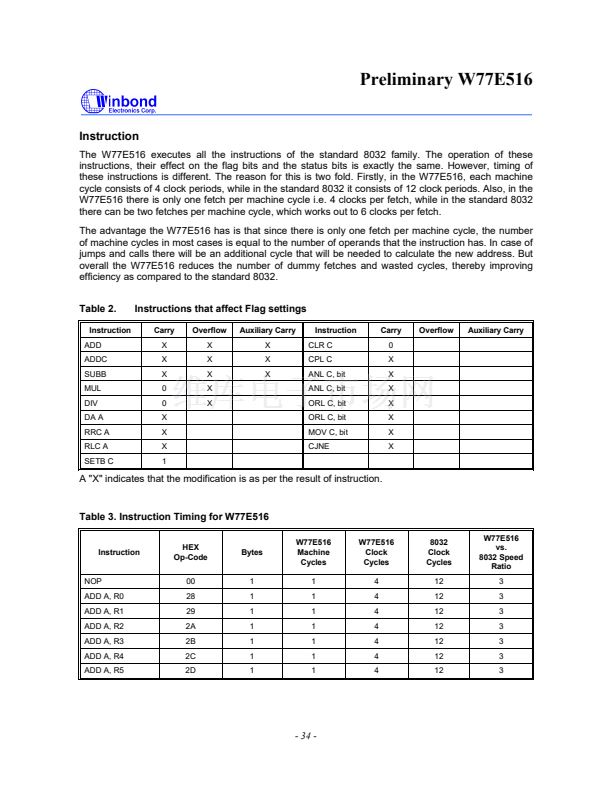
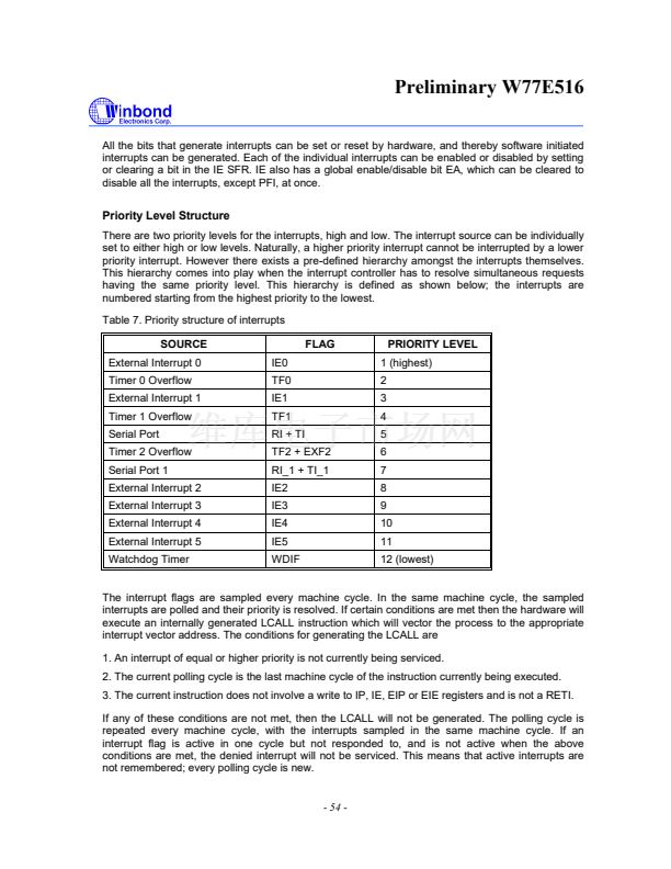
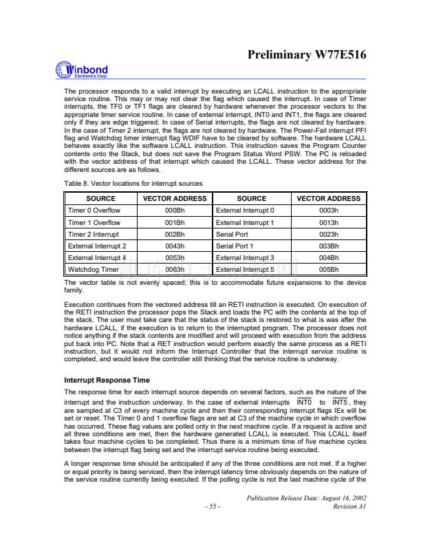
The W77E516 has a two priority level interrupt structure with 12 interrupt sources. Each of the interrupt
sources has an individual priority bit, flag, interrupt vector and enable bit. In addition, the interrupts can
be globally enabled or disabled.
Interrupt Sources
The External Interrupts INT0 and INT1 can be either edge triggered or level triggered,
depending on bits IT0 and IT1. The bits IE0 and IE1 in the TCON register are the flags which are
checked to generate the interrupt. In the edge triggered mode, the INTx inputs are sampled in every
machine cycle. If the sample is high in one cycle and low in the next, then a high to low transition is
detected and the interrupts request flag IEx in TCON or EXIF is set. The flag bit requests the
interrupt. Since the external interrupts are sampled every machine cycle, they have to be held high
or low for at least one complete machine cycle. The IEx flag is automatically cleared when the
service routine is called. If the level triggered mode is selected, then the requesting source has to
hold the pin low till the interrupt is serviced. The IEx flag will not be cleared by the hardware on
entering the service routine. If the interrupt continues to be held low even after the service routine is
completed, then the processor may acknowledge another interrupt request from the same source.
Note that the external interrupts INT2 to INT5 are edge triggered only. By default, the individual
interrupt flag corresponding to external interrupt 2 to 5 must be cleared manually by software. It can
be configured with hardware cleared by setting the corresponding bit HCx in the T2MOD register.
For instance, if HC2 is set hardware will clear IE2 flag after program enters the interrupt 2 service
routine.
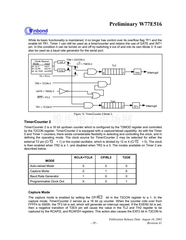
The Timer 0 and 1 Interrupts are generated by the TF0 and TF1 flags. These flags are set by the
overflow in the Timer 0 and Timer 1. The TF0 and TF1 flags are automatically cleared by the
hardware when the timer interrupt is serviced. The Timer 2 interrupt is generated by a logical OR of
the TF2 and the EXF2 flags. These flags are set by overflow or capture/reload events in the timer 2
operation. The hardware does not clear these flags when a timer 2 interrupt is executed. Software
has to resolve the cause of the interrupt between TF2 and EXF2 and clear the appropriate flag.
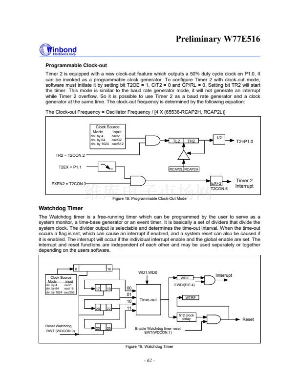
The Watchdog timer can be used as a system monitor or a simple timer. In either case, when the
time-out count is reached, the Watchdog timer interrupt flag WDIF (WDCON.3) is set. If the
interrupt is enabled by the enable bit EIE.4, then an interrupt will occur.
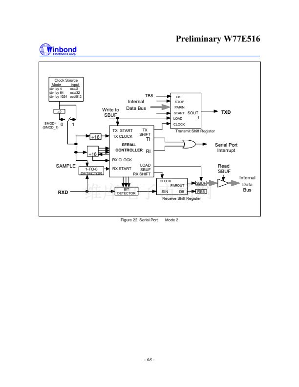
The Serial block can generate interrupts on reception or transmission. There are two interrupt
sources from the Serial block, which are obtained by the RI and TI bits in the SCON SFR and RI_1
and TI_1 in the SCON1 SFR. These bits are not automatically cleared by the hardware, and the
user will have to clear these bits using software.
- 53 -
Publication Release Date: August 16, 2002
Revision A1


 1
1
 2
2
 3
3
 4
4
 5
5
 6
6
 7
7
 8
8
 9
9
 10
10
 11
11
 12
12
 13
13
 14
14
 15
15
 16
16
 17
17
 18
18
 19
19
 20
20
 21
21
 22
22
 23
23
 24
24
 25
25
 26
26
 27
27
 28
28
 29
29
 30
30
 31
31
 32
32
 33
33
 34
34
 35
35
 36
36
 37
37
 38
38
 39
39
 40
40
 41
41
 42
42
 43
43
 44
44
 45
45
 46
46
 47
47
 48
48
 49
49
 50
50
 51
51
 52
52
 53
53
 54
54
 55
55
 56
56
 57
57
 58
58
 59
59
 60
60
 61
61
 62
62
 63
63
 64
64
 65
65
 66
66
 67
67
 68
68
 69
69
 70
70
 71
71
 72
72
 73
73
 74
74
 75
75
 76
76
 77
77
 78
78
 79
79
 80
80
 81
81
 82
82
 83
83
 84
84
 85
85
