Preliminary W77E516
(if the global interrupt enable is set and other interrupt requirements are met). Software or
any reset can clear this bit.
WTRF: WDCON.2 - Watchdog Timer Reset flag. This bit is set whenever a watchdog reset occurs.
This bit is useful for determined the cause of a reset. Software must read it, and clear it
manually. A Power-fail reset will clear this bit. If EWT = 0, then this bit will not be affected by
the watchdog timer.
EWT: WDCON.1 - Enable Watchdog timer Reset. This bit when set to 1 will enable the Watchdog
timer reset function. Setting this bit to 0 will disable the Watchdog timer reset function, but
will leave the timer running
RWT: WDCON.0 - Reset Watchdog Timer. This bit is used to clear the Watchdog timer and to
restart it. This bit is self-clearing, so after the software writes 1 to it the hardware will
automatically clear it. If the Watchdog timer reset is enabled, then the RWT has to be set by
the user within 512 clocks of the time-out. If this is not done then a Watchdog timer reset will
occur.
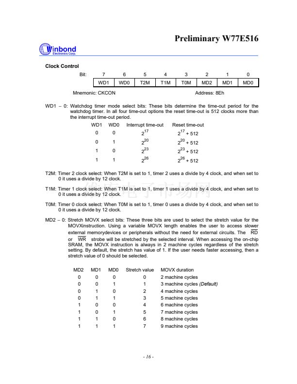
Clock Control
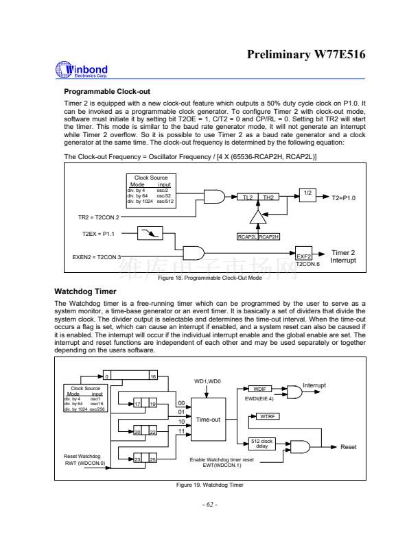
WD1, WD0: CKCON.7, CKCON.6 - Watchdog Timer Mode select bits. These two bits select the
time-out interval for the watchdog timer. The reset time is 512 clock longer than the interrupt time-
out value.
The default Watchdog time-out is 2 clocks, which is the shortest time-out period. The EWT,
WDIF and RWT bits are protected by the Timed Access procedure. This prevents software from
accidentally enabling or disabling the watchdog timer. More importantly, it makes it highly
improbable that errant code can enable or disable the watchdog timer.
17
Serial Port
Serial port in the W77E516 is a full duplex port. The W77E516 provides the user with additional
features such as the Frame Error Detection and the Automatic Address Recognition. The serial ports
are capable of synchronous as well as asynchronous communication. In Synchronous mode the
W77E516 generates the clock and operates in a half duplex mode. In the asynchronous mode, full
duplex operation is available. This means that it can simultaneously transmit and receive data. The
transmit register and the receive buffer are both addressed as SBUF Special Function Register.
However any write to SBUF will be to the transmit register, while a read from SBUF will be from the
receive buffer register. The serial port can operate in four different modes as described below.
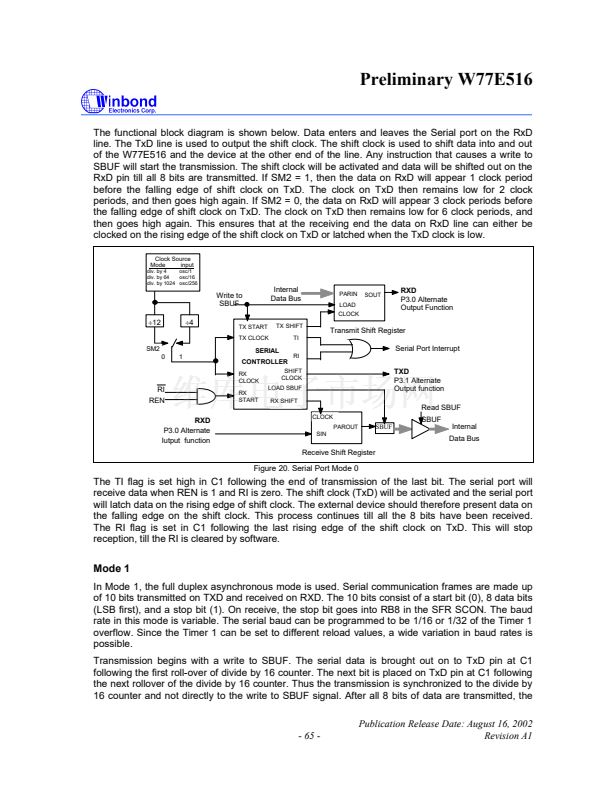
Mode 0
This mode provides synchronous communication with external devices. In this mode serial data is
transmitted and received on the RXD line. TXD is used to transmit the shift clock. The TxD clock is
provided by the W77E516 whether the device is transmitting or receiving. This mode is therefore a
half duplex mode of serial communication. In this mode, 8 bits are transmitted or received per
frame. The LSB is transmitted/received first. The baud rate is fixed at 1/12 or 1/4 of the oscillator
frequency. This baud rate is determined by the SM2 bit (SCON.5). When this bit is set to 0, then the
serial port runs at 1/12 of the clock. When set to 1, the serial port runs at 1/4 of the clock. This
additional facility of programmable baud rate in mode 0 is the only difference between the standard
8051 and the W77E516.
- 64 -


 1
1
 2
2
 3
3
 4
4
 5
5
 6
6
 7
7
 8
8
 9
9
 10
10
 11
11
 12
12
 13
13
 14
14
 15
15
 16
16
 17
17
 18
18
 19
19
 20
20
 21
21
 22
22
 23
23
 24
24
 25
25
 26
26
 27
27
 28
28
 29
29
 30
30
 31
31
 32
32
 33
33
 34
34
 35
35
 36
36
 37
37
 38
38
 39
39
 40
40
 41
41
 42
42
 43
43
 44
44
 45
45
 46
46
 47
47
 48
48
 49
49
 50
50
 51
51
 52
52
 53
53
 54
54
 55
55
 56
56
 57
57
 58
58
 59
59
 60
60
 61
61
 62
62
 63
63
 64
64
 65
65
 66
66
 67
67
 68
68
 69
69
 70
70
 71
71
 72
72
 73
73
 74
74
 75
75
 76
76
 77
77
 78
78
 79
79
 80
80
 81
81
 82
82
 83
83
 84
84
 85
85
