ISL6612A, ISL6613A
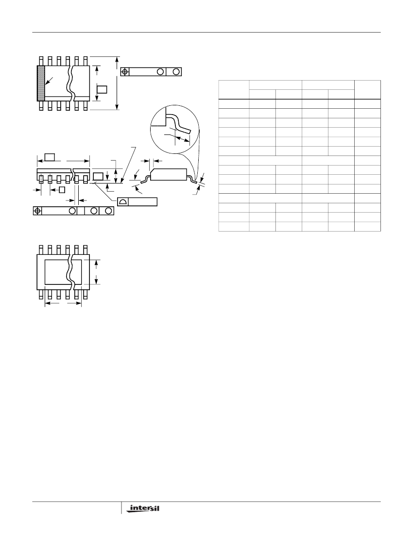
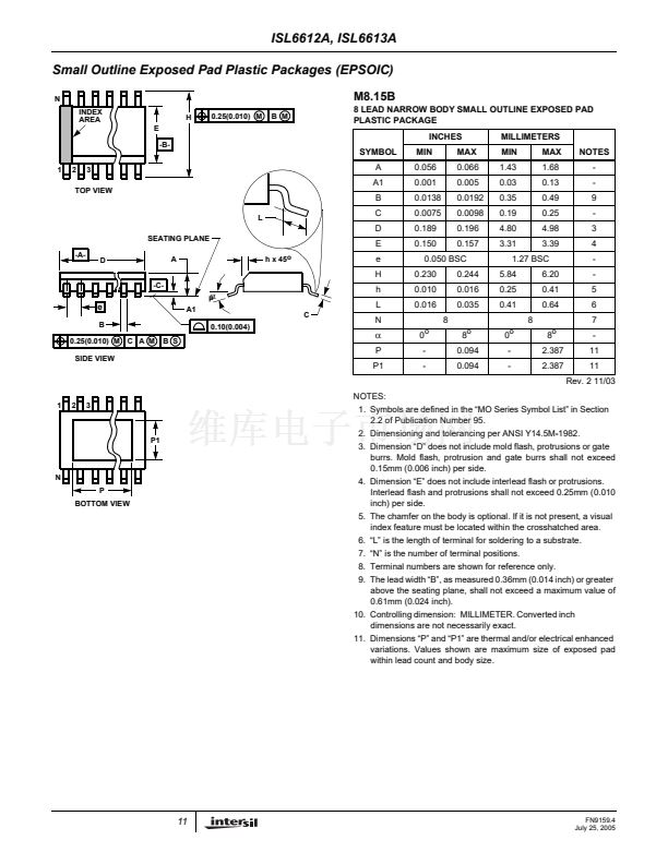
Small Outline Exposed Pad Plastic Packages (EPSOIC)
N
INDEX
AREA
E
-B-
1
2
3
H
0.25(0.010) M
B M
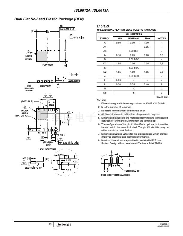
M8.15B
8 LEAD NARROW BODY SMALL OUTLINE EXPOSED PAD
PLASTIC PACKAGE
INCHES
SYMBOL
A
A1
TOP VIEW
MILLIMETERS
MIN
1.43
0.03
0.35
0.19
4.80
3.31
MAX
1.68
0.13
0.49
0.25
4.98
3.39
NOTES
-
-
9
-
3
4
-
-
5
6
7
8
o
2.387
2.387
-
11
11
Rev. 2 11/03
MIN
0.056
0.001
0.0138
0.0075
0.189
0.150
MAX
0.066
0.005
0.0192
0.0098
0.196
0.157
B
L
SEATING PLANE
C
D
E
h x 45
o
-A-
D
-C-
A
e
H
0.050 BSC
0.230
0.010
0.016
8
0
o
-
-
8
o
0.094
0.094
0.244
0.016
0.035
1.27 BSC
5.84
0.25
0.41
8
0
o
-
-
6.20
0.41
0.64
伪
碌
A1
0.10(0.004)
C
h
L
N
e
B
0.25(0.010) M
SIDE VIEW
C A M
B S
伪
P
P1
NOTES:
1
2
3
1. Symbols are defined in the 鈥淢O Series Symbol List鈥?in Section
2.2 of Publication Number 95.
P1
2. Dimensioning and tolerancing per ANSI Y14.5M-1982.
3. Dimension 鈥淒鈥?does not include mold flash, protrusions or gate
burrs. Mold flash, protrusion and gate burrs shall not exceed
0.15mm (0.006 inch) per side.
4. Dimension 鈥淓鈥?does not include interlead flash or protrusions.
Interlead flash and protrusions shall not exceed 0.25mm (0.010
inch) per side.
5. The chamfer on the body is optional. If it is not present, a visual
index feature must be located within the crosshatched area.
6. 鈥淟鈥?is the length of terminal for soldering to a substrate.
7. 鈥淣鈥?is the number of terminal positions.
8. Terminal numbers are shown for reference only.
9. The lead width 鈥淏鈥? as measured 0.36mm (0.014 inch) or greater
above the seating plane, shall not exceed a maximum value of
0.61mm (0.024 inch).
10. Controlling dimension: MILLIMETER. Converted inch
dimensions are not necessarily exact.
11. Dimensions 鈥淧鈥?and 鈥淧1鈥?are thermal and/or electrical enhanced
variations. Values shown are maximum size of exposed pad
within lead count and body size.
N
P
BOTTOM VIEW
11
FN9159.4
July 25, 2005


 1
1
 2
2
 3
3
 4
4
 5
5
 6
6
 7
7
 8
8
 9
9
 10
10
 11
11
 12
12
