ISL5416
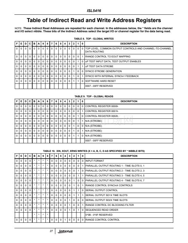
Tables of Top Level Registers
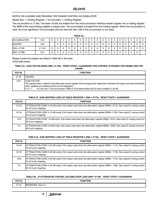
In the tables below 鈥渞eset state鈥?indicates the register
contents after a HW reset or a SW hard reset. Unless
noted, a soft channel reset does not clear register
contents. A soft channel reset does clear the slave
registers of a master/slave pair (such as channel data
path control) but does not clear the master.
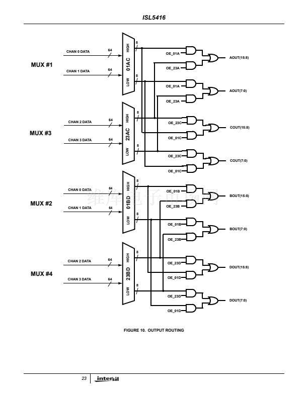
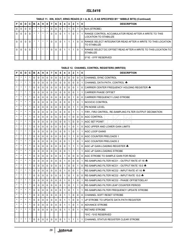
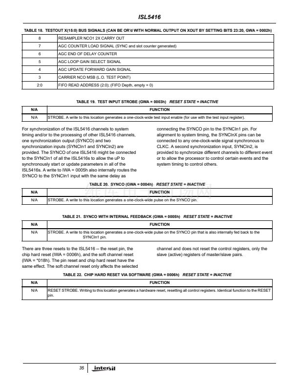
This register controls the output SYNC signal polarity, the
output clock rate and polarity, output data modes, and
channel cascading.
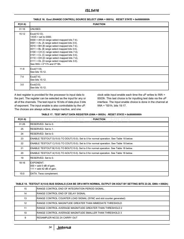
TABLE 15. COMMON OUTPUT CONTROL FUNCTIONS (GWA = 0000h)
RESET STATE = 0x00000001h
P(31:0)
31
FUNCTION
ENABLE SERIAL OUTPUT.
1 = serial output mode is enabled. The DOUT parallel data bus is replaced with 4 serial output busses -- one per channel. See 0*06h
- 0*08h and Table 30.
RESERVED. Set to 0.
SCLK RESET.
1 = serial clock divider is reset by SYNCInX if the reset serial output bit is set in IWA = *000h, bits 13 or 29 of any of the 4 channels.
SCLK POLARITY.
1 = Low to High transitions at the center of the data bit.
0 = High to Low transitions at the center of the data bit.
SCLK RATE.
000 = SCLK DIsabled.
001 = input clock rate.
010 = input clock rate / 2.
011 = input clock rate / 4.
100 = input clock rate / 8.
101 = input clock rate /16.
RESERVED. Set to 0.
ROUTE CHANNEL 2 TO CHANNEL 3.
1 = route the output of FIR2 of channel 2 to the input of the CIC to FIR1 gain block in channel 3.
ROUTE CHANNEL 1 TO CHANNEL 2.
1 = route the output of FIR2 of channel 1 to the input of the CIC to FIR1 gain block in channel 2.
ROUTE CHANNEL 0 TO CHANNEL 1.
1 = route the output of FIR2 of channel 0 to the input of the CIC to FIR1 gain block in channel 1.
CHANNEL 0 EXTERNAL AGC SOURCE SELECT.
0 = when bit 14 is set, Channel 1 controls Channel 0 gain.
1 = when bit 14 is set, Channel 3 controls Channel 0 gain.
CHANNEL 2 EXTERNAL/INTERNAL GAIN CONTROL.
1 = Channel 2 gain is controlled by Channel 3.
CHANNEL 1 EXTERNAL/INTERNAL GAIN CONTROL.
1 = Channel 1 gain is controlled by Channel 3.
CHANNEL 0 EXTERNAL/INTERNAL GAIN CONTROL.
1 = Channel 0 gain is controlled by Channel 3 or Channel 1 depending on the state of bit 17.
CLKO2 OR INTRPT.
1 = CLKO2/INTRPT is INTRPT (2 clock period wide pulse).
0 = CLKO2/INTRPT is CLKO2.
NOTE: For INTRPT IWA = 0*0Ah, bit 31 must be set for the channel that is the interrupt source..
FSYNCX POLARITY.
0 = active high
1 = active low.
30
29
28
27:25
24:21
20
19
18
17
16
15
14
13
12
32


 1
1
 2
2
 3
3
 4
4
 5
5
 6
6
 7
7
 8
8
 9
9
 10
10
 11
11
 12
12
 13
13
 14
14
 15
15
 16
16
 17
17
 18
18
 19
19
 20
20
 21
21
 22
22
 23
23
 24
24
 25
25
 26
26
 27
27
 28
28
 29
29
 30
30
 31
31
 32
32
 33
33
 34
34
 35
35
 36
36
 37
37
 38
38
 39
39
 40
40
 41
41
 42
42
 43
43
 44
44
 45
45
 46
46
 47
47
 48
48
 49
49
 50
50
 51
51
 52
52
 53
53
 54
54
 55
55
 56
56
 57
57
 58
58
 59
59
 60
60
 61
61
 62
62
 63
63
 64
64
 65
65
 66
66
 67
67
 68
68
 69
69
 70
70
 71
71
