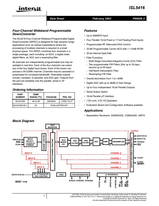
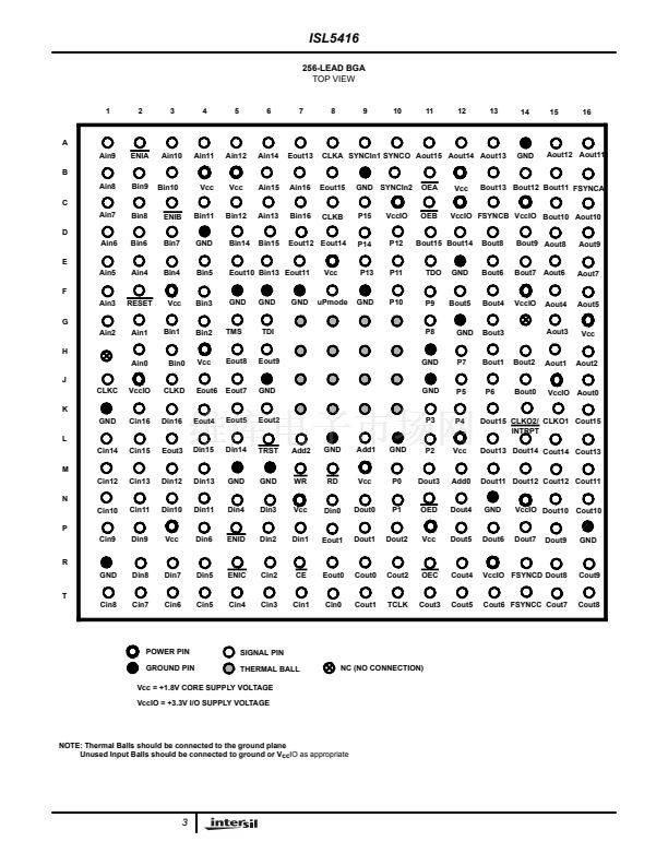
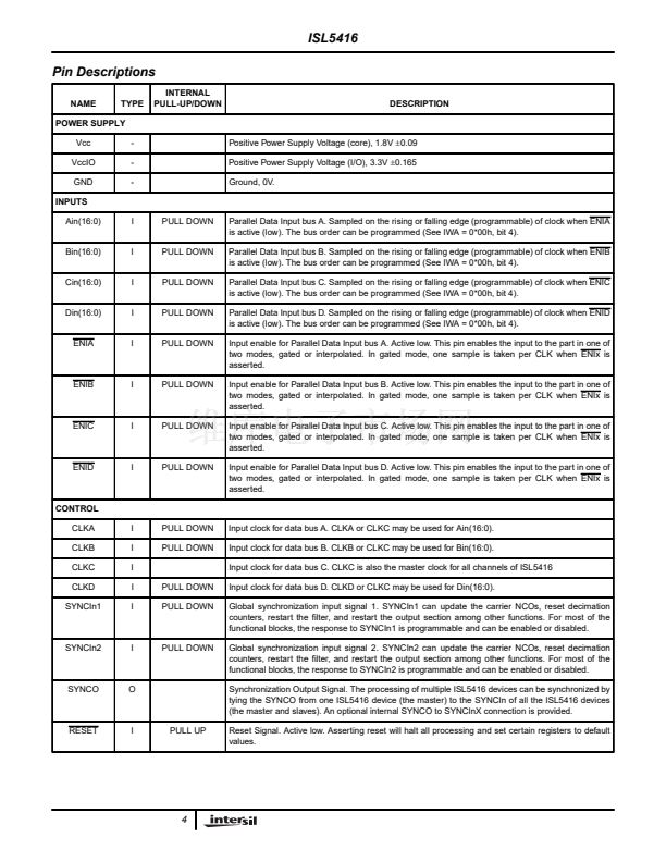
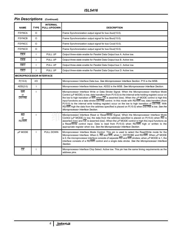
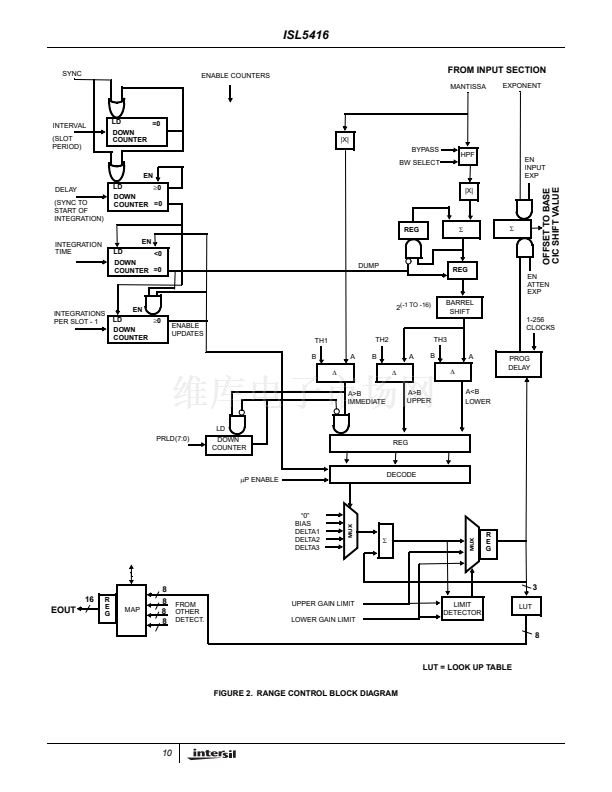
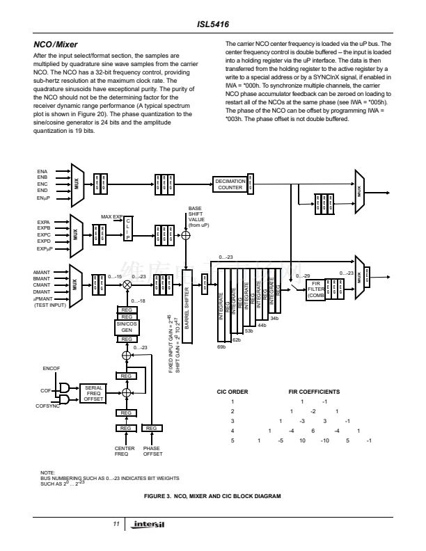
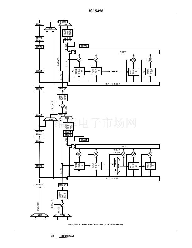
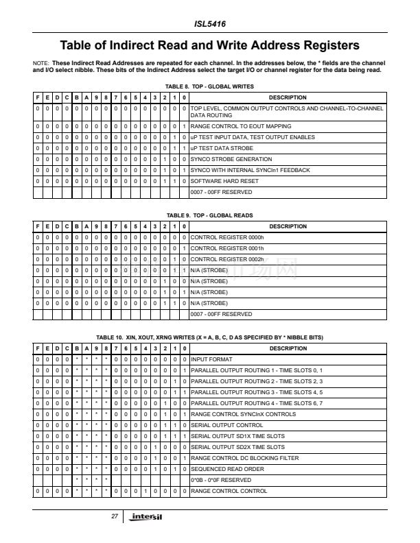
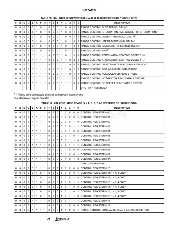
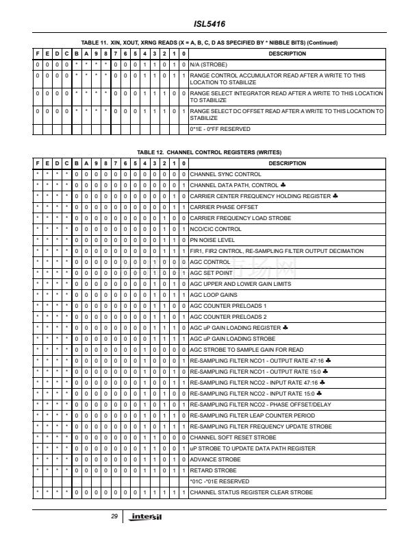
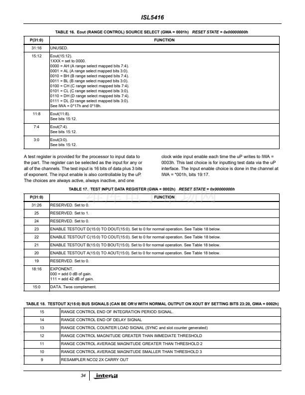
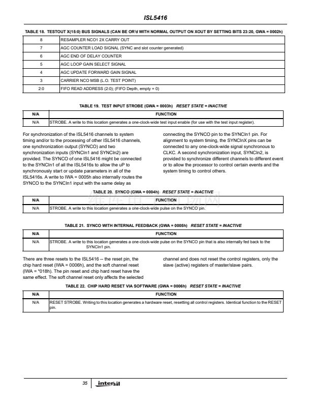
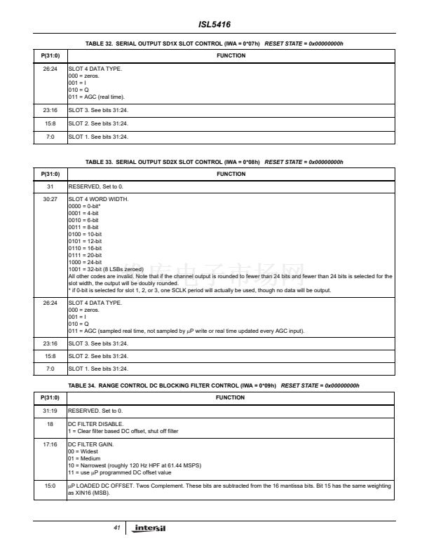
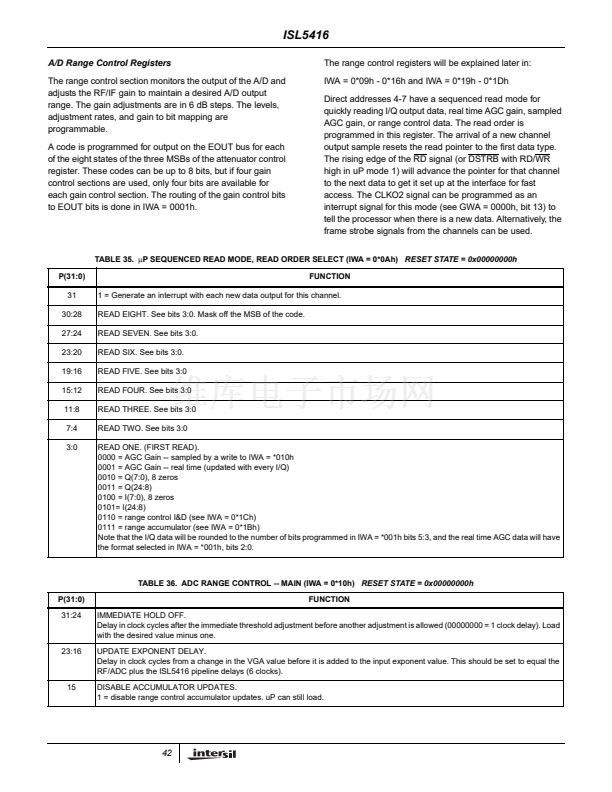
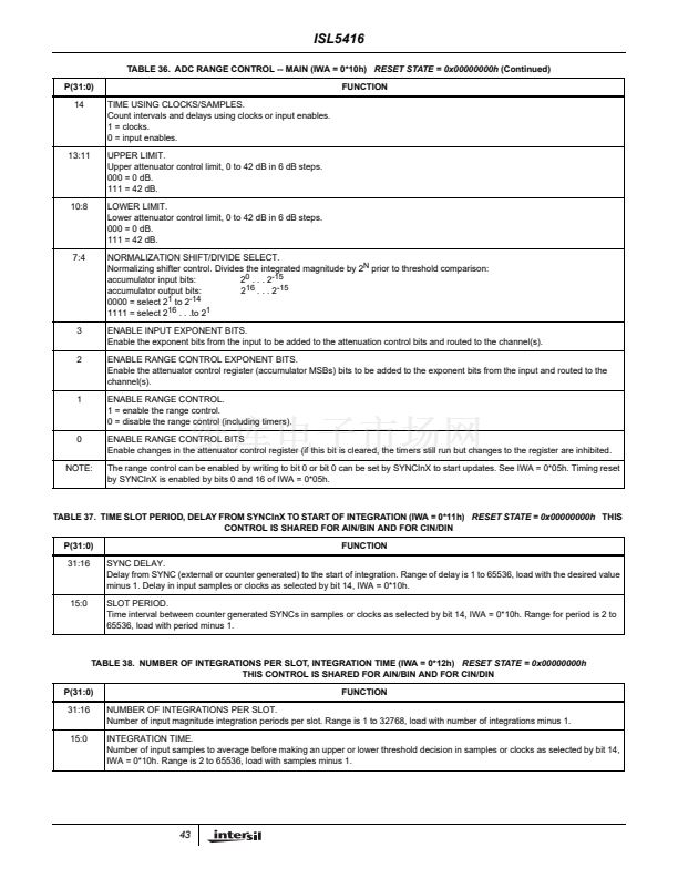
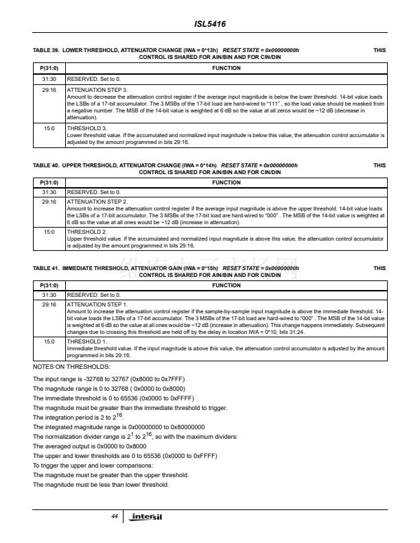
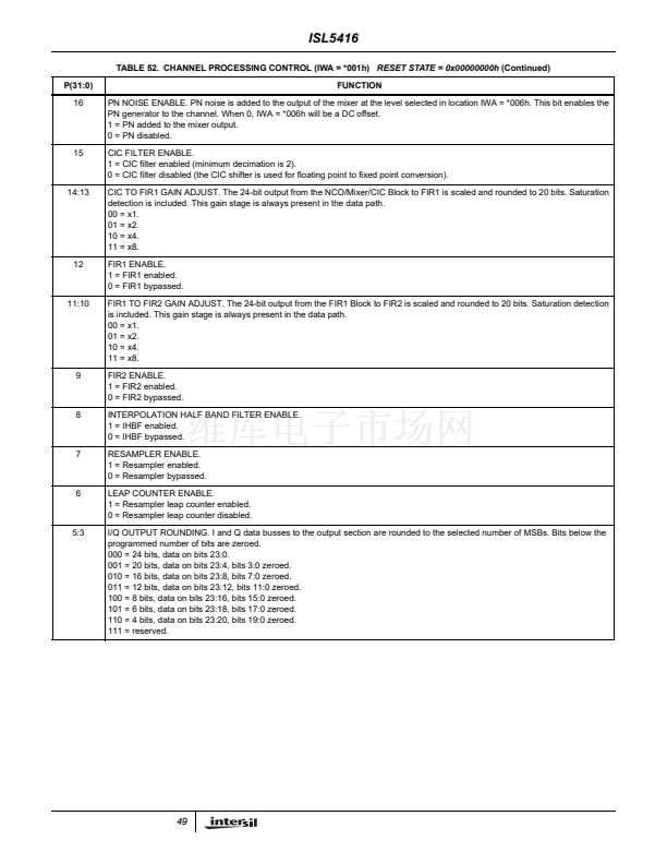
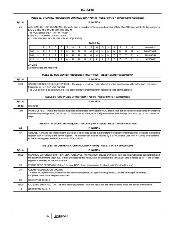
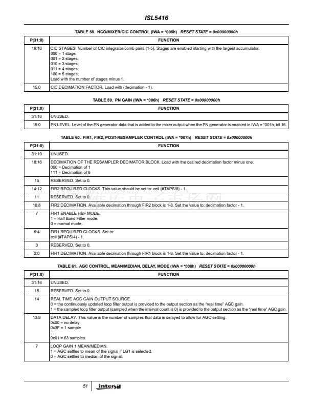
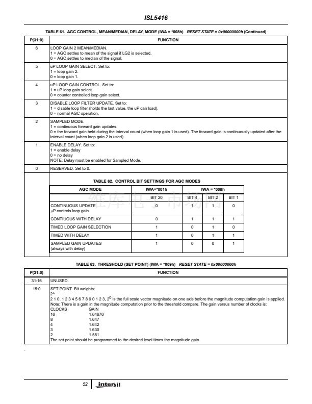
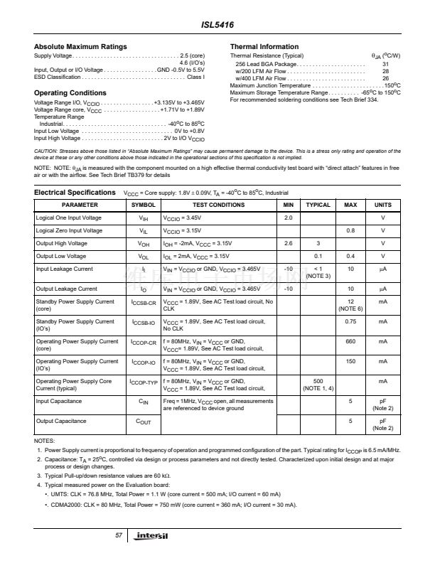
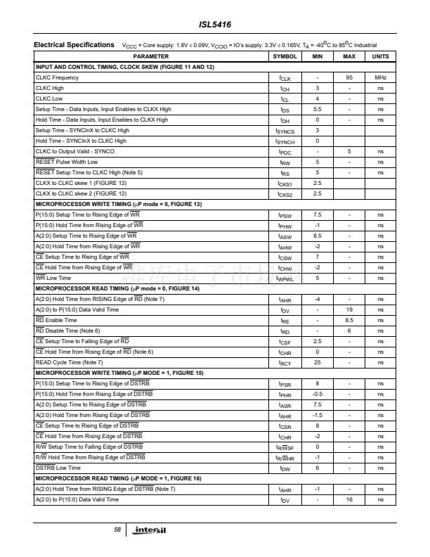
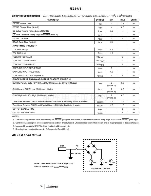
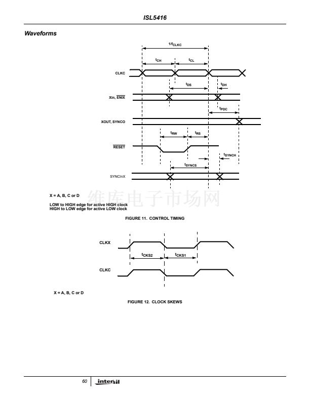
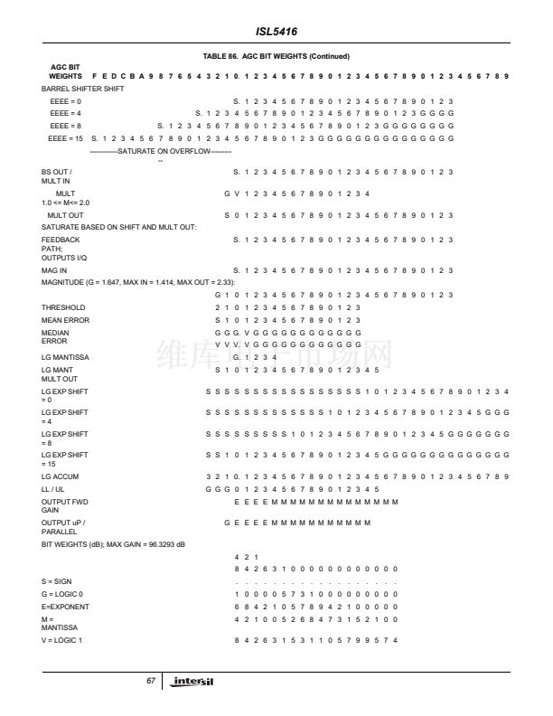
ISL5416
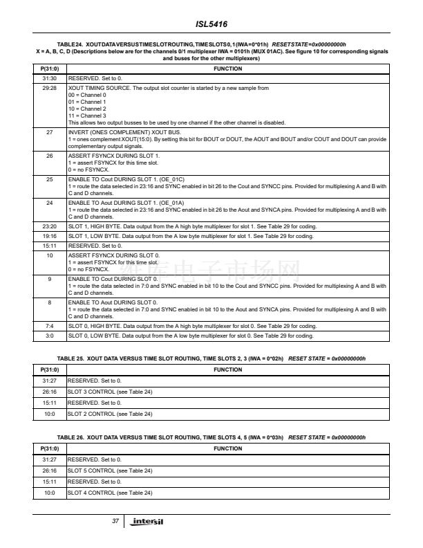
TABLE 24. XOUT DATA VERSUS TIME SLOT ROUTING, TIME SLOTS 0, 1 (IWA = 0*01h)
RESET STATE = 0x00000000h
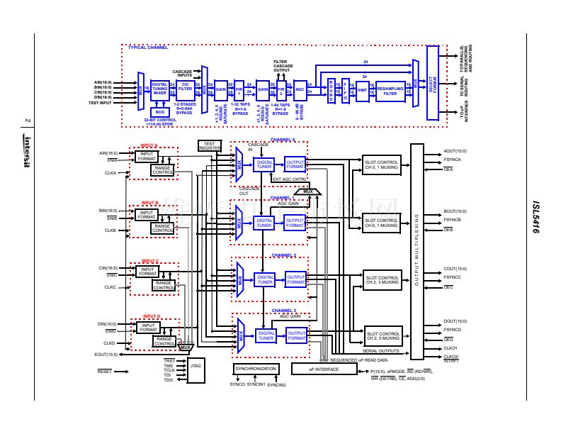
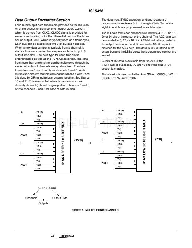
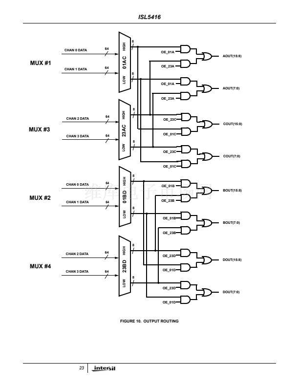
X = A, B, C, D (Descriptions below are for the channels 0/1 multiplexer IWA = 0101h (MUX 01AC). See figure 10 for corresponding signals
and buses for the other multiplexers)
P(31:0)
31:30
29:28
RESERVED. Set to 0.
XOUT TIMING SOURCE. The output slot counter is started by a new sample from
00 = Channel 0
01 = Channel 1
10 = Channel 2
11 = Channel 3
This allows two output busses to be used by one channel if the other channel is disabled.
INVERT (ONES COMPLEMENT) XOUT BUS.
1 = ones complement XOUT(15:0). By setting this bit for BOUT or DOUT, the AOUT and BOUT and/or COUT and DOUT can provide
complementary output signals.
ASSERT FSYNCX DURING SLOT 1.
1 = assert FSYNCX for this time slot.
0 = no FSYNCX.
ENABLE TO Cout DURING SLOT 1. (OE_01C)
1 = route the data selected in 23:16 and SYNC enabled in bit 26 to the Cout and SYNCC pins. Provided for multiplexing A and B with
C and D channels.
ENABLE TO Aout DURING SLOT 1. (OE_01A)
1 = route the data selected in 23:16 and SYNC enabled in bit 26 to the Aout and SYNCA pins. Provided for multiplexing A and B with
C and D channels.
SLOT 1, HIGH BYTE. Data output from the A high byte multiplexer for slot 1. See Table 29 for coding.
SLOT 1, LOW BYTE. Data output from the A low byte multiplexer for slot 1. See Table 29 for coding.
RESERVED. Set to 0.
ASSERT FSYNCX DURING SLOT 0.
1 = assert FSYNCX for this time slot.
0 = no FSYNCX.
ENABLE TO Cout DURING SLOT 0.
1 = route the data selected in 7:0 and SYNC enabled in bit 10 to the Cout and SYNCC pins. Provided for multiplexing A and B with
C and D channels.
ENABLE TO Aout DURING SLOT 0.
1 = route the data selected in 7:0 and SYNC enabled in bit 10 to the Aout and SYNCA pins. Provided for multiplexing A and B with
C and D channels.
SLOT 0, HIGH BYTE. Data output from the A high byte multiplexer for slot 0. See Table 29 for coding.
SLOT 0, LOW BYTE. Data output from the A low byte multiplexer for slot 0. See Table 29 for coding.
FUNCTION
27
26
25
24
23:20
19:16
15:11
10
9
8
7:4
3:0
TABLE 25. XOUT DATA VERSUS TIME SLOT ROUTING, TIME SLOTS 2, 3 (IWA = 0*02h)
RESET STATE = 0x00000000h
P(31:0)
31:27
26:16
15:11
10:0
RESERVED. Set to 0.
SLOT 3 CONTROL (see Table 24)
RESERVED. Set to 0.
SLOT 2 CONTROL (see Table 24)
FUNCTION
TABLE 26. XOUT DATA VERSUS TIME SLOT ROUTING, TIME SLOTS 4, 5 (IWA = 0*03h)
RESET STATE = 0x00000000h
P(31:0)
31:27
26:16
15:11
10:0
RESERVED. Set to 0.
SLOT 5 CONTROL (see Table 24)
RESERVED. Set to 0.
SLOT 4 CONTROL (see Table 24)
FUNCTION
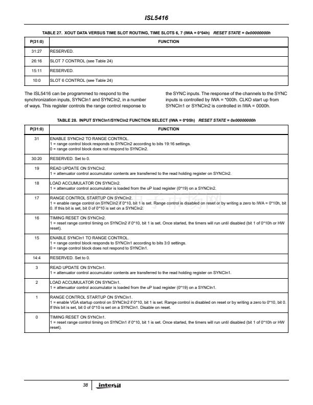
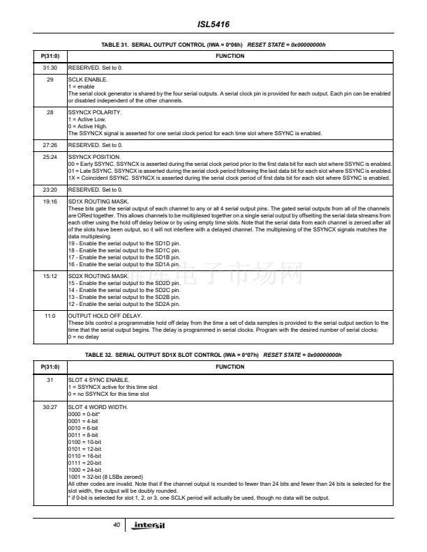
37


 1
1
 2
2
 3
3
 4
4
 5
5
 6
6
 7
7
 8
8
 9
9
 10
10
 11
11
 12
12
 13
13
 14
14
 15
15
 16
16
 17
17
 18
18
 19
19
 20
20
 21
21
 22
22
 23
23
 24
24
 25
25
 26
26
 27
27
 28
28
 29
29
 30
30
 31
31
 32
32
 33
33
 34
34
 35
35
 36
36
 37
37
 38
38
 39
39
 40
40
 41
41
 42
42
 43
43
 44
44
 45
45
 46
46
 47
47
 48
48
 49
49
 50
50
 51
51
 52
52
 53
53
 54
54
 55
55
 56
56
 57
57
 58
58
 59
59
 60
60
 61
61
 62
62
 63
63
 64
64
 65
65
 66
66
 67
67
 68
68
 69
69
 70
70
 71
71
