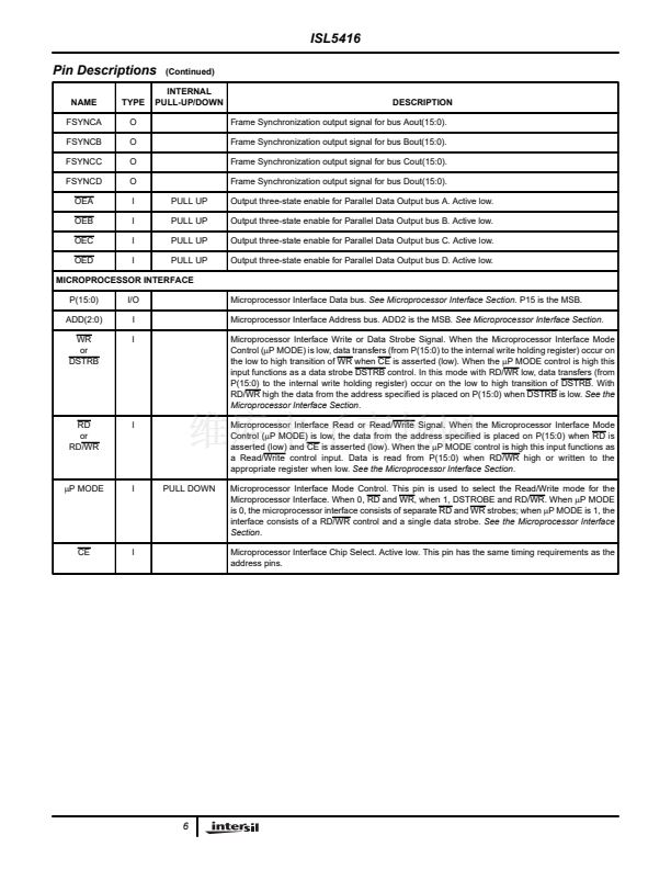
ISL5416
TABLE 29. HIGH, LOW BYTE DATA TYPE CODES (AFTER
ROUNDING IN THE CHANNEL)
CODE
0000
0001
0010
0011
0100
0101
0110
0111
1000
1001
1010
1011
1100
1101
1110
1111
CHANNEL 0, CHANNEL CHANNEL 2, CHANNEL
1 MUXES
3 MUXES
CH 0 I(23:16)
CH 0 I(15:8)
CH 0 I(7:0)
CH 0 Q(23:16)
CH 0 Q(15:8)
CH 0 Q(7:0)
CH 0 AGC(15:8)
CH 0 AGC(7:0)
CH 1 I(23:16)
CH 1 I(15:8)
CH 1 I(7:0)
CH 1 Q(23:16)
CH 1 Q(15:8)
CH 1 Q(7:0)
CH 1 AGC(15:8)
CH 1 AGC(7:0)
CH 2 I(23:16)
CH 2 I(15:8)
CH 2 I(7:0)
CH 2 Q(23:16)
CH 2 Q(15:8)
CH 2 Q(7:0)
CH 2 AGC(15:8)
CH 2 AGC(7:0)
CH 3 I(23:16)
CH 3 I(15:8)
CH 3 I(7:0)
SCLKX
SSYNCX
SD1X
SD2X
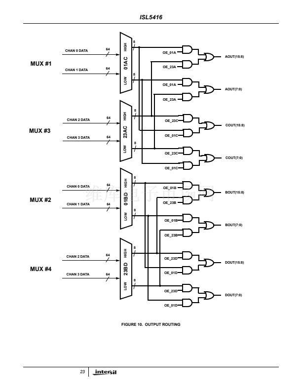
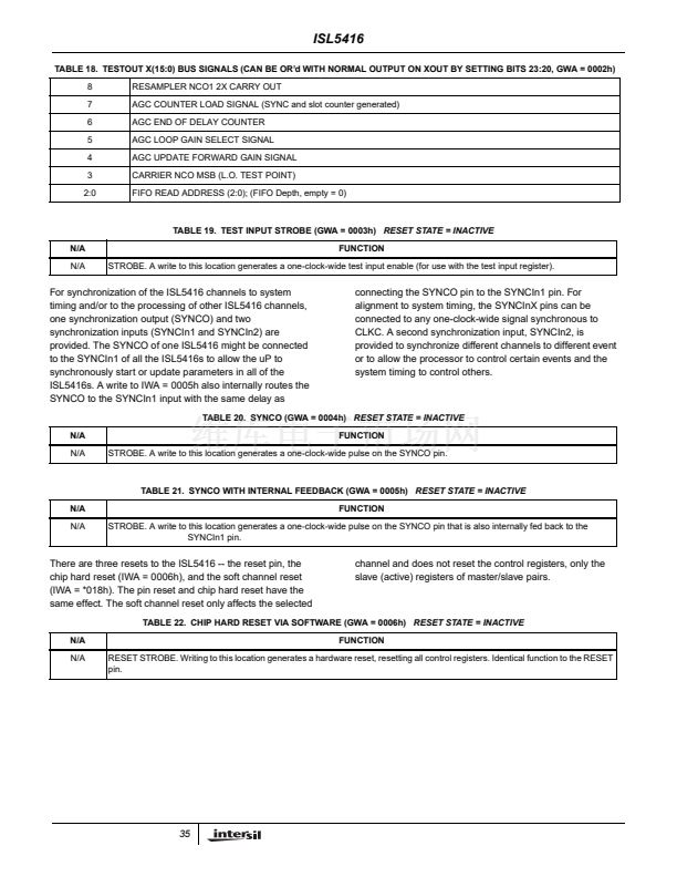
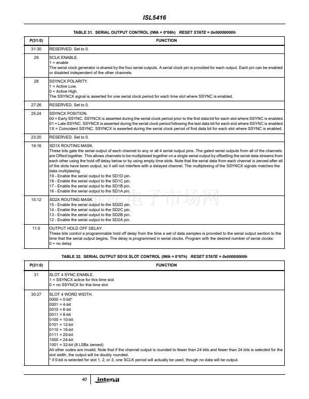
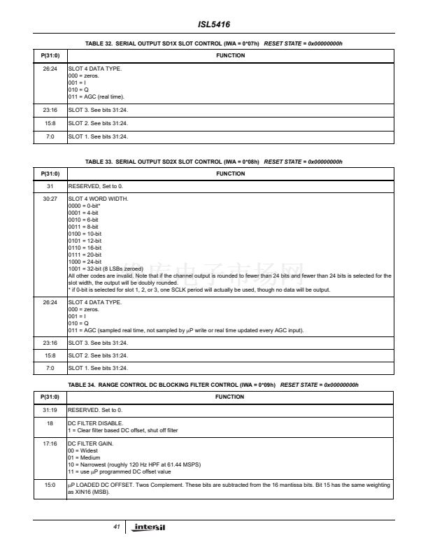
Serial Output:
When bit 31 of GWA = 0000h is set, the DOUT bus is used
for serial outputs.
Four bits are allocated to each channel as follows:
TABLE 30. SERIAL OUTPUT BITS ALLOCATION
CHANNEL 0
DOUT0
DOUT1
DOUT2
DOUT3
CHANNEL 1
DOUT4
DOUT5
DOUT6
DOUT7
CHANNEL 2
DOUT8
DOUT9
DOUT10
DOUT11
CHANNEL 3
DOUT12
DOUT13
DOUT14
DOUT15
A common serial clock generator is used for all four outputs,
so the four SCLKs are synchronous. Four separate outputs
are provided to simplify PWB routing. Each SCLK output can
be separately enabled, so that unused clock outputs can be
turned off.
Serial outputs are always MSB first.
CH 3 Q(23:16)
CH 3 Q(15:8)
CH 3 Q(7:0)
CH 3 AGC(15:8)
CH 3 AGC(7:0)
Addresses 0106h to 0108h control the serial output from
channel 0.
Addresses 0206h to 0208h control the serial output from
channel 1.
Addresses 0406h to 0408h control the serial output from
channel 2.
Addresses 0806h to 0808h control the serial output from
channel 3.
39


 1
1
 2
2
 3
3
 4
4
 5
5
 6
6
 7
7
 8
8
 9
9
 10
10
 11
11
 12
12
 13
13
 14
14
 15
15
 16
16
 17
17
 18
18
 19
19
 20
20
 21
21
 22
22
 23
23
 24
24
 25
25
 26
26
 27
27
 28
28
 29
29
 30
30
 31
31
 32
32
 33
33
 34
34
 35
35
 36
36
 37
37
 38
38
 39
39
 40
40
 41
41
 42
42
 43
43
 44
44
 45
45
 46
46
 47
47
 48
48
 49
49
 50
50
 51
51
 52
52
 53
53
 54
54
 55
55
 56
56
 57
57
 58
58
 59
59
 60
60
 61
61
 62
62
 63
63
 64
64
 65
65
 66
66
 67
67
 68
68
 69
69
 70
70
 71
71
