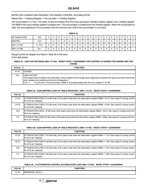
ISL5416
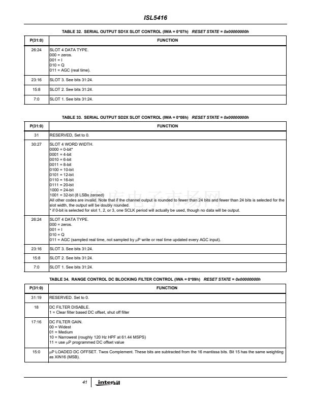
TABLE 32. SERIAL OUTPUT SD1X SLOT CONTROL (IWA = 0*07h)
RESET STATE = 0x00000000h
P(31:0)
26:24
SLOT 4 DATA TYPE.
000 = zeros.
001 = I
010 = Q
011 = AGC (real time).
SLOT 3. See bits 31:24.
SLOT 2. See bits 31:24.
SLOT 1. See bits 31:24.
FUNCTION
23:16
15:8
7:0
TABLE 33. SERIAL OUTPUT SD2X SLOT CONTROL (IWA = 0*08h)
RESET STATE = 0x00000000h
P(31:0)
31
30:27
RESERVED, Set to 0.
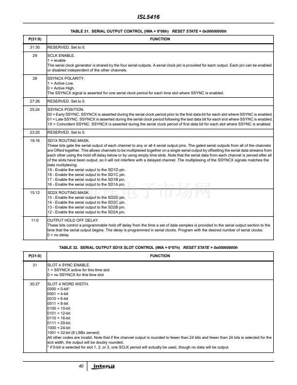
SLOT 4 WORD WIDTH.
0000 = 0-bit*
0001 = 4-bit
0010 = 6-bit
0011 = 8-bit
0100 = 10-bit
0101 = 12-bit
0110 = 16-bit
0111 = 20-bit
1000 = 24-bit
1001 = 32-bit (8 LSBs zeroed)
All other codes are invalid. Note that if the channel output is rounded to fewer than 24 bits and fewer than 24 bits is selected for the
slot width, the output will be doubly rounded.
* if 0-bit is selected for slot 1, 2, or 3, one SCLK period will actually be used, though no data will be output.
SLOT 4 DATA TYPE.
000 = zeros.
001 = I
010 = Q
011 = AGC (sampled real time, not sampled by
碌P
write or real time updated every AGC input).
SLOT 3. See bits 31:24.
SLOT 2. See bits 31:24.
SLOT 1. See bits 31:24.
TABLE 34. RANGE CONTROL DC BLOCKING FILTER CONTROL (IWA = 0*09h)
RESET STATE = 0x00000000h
P(31:0)
31:19
18
RESERVED. Set to 0.
DC FILTER DISABLE.
1 = Clear filter based DC offset, shut off filter
DC FILTER GAIN.
00 = Widest
01 = Medium
10 = Narrowest (roughly 120 Hz HPF at 61.44 MSPS)
11 = use
碌P
programmed DC offset value
碌P
LOADED DC OFFSET. Twos Complement. These bits are subtracted from the 16 mantissa bits. Bit 15 has the same weighting
as XIN16 (MSB).
FUNCTION
FUNCTION
26:24
23:16
15:8
7:0
17:16
15:0
41


 1
1
 2
2
 3
3
 4
4
 5
5
 6
6
 7
7
 8
8
 9
9
 10
10
 11
11
 12
12
 13
13
 14
14
 15
15
 16
16
 17
17
 18
18
 19
19
 20
20
 21
21
 22
22
 23
23
 24
24
 25
25
 26
26
 27
27
 28
28
 29
29
 30
30
 31
31
 32
32
 33
33
 34
34
 35
35
 36
36
 37
37
 38
38
 39
39
 40
40
 41
41
 42
42
 43
43
 44
44
 45
45
 46
46
 47
47
 48
48
 49
49
 50
50
 51
51
 52
52
 53
53
 54
54
 55
55
 56
56
 57
57
 58
58
 59
59
 60
60
 61
61
 62
62
 63
63
 64
64
 65
65
 66
66
 67
67
 68
68
 69
69
 70
70
 71
71
