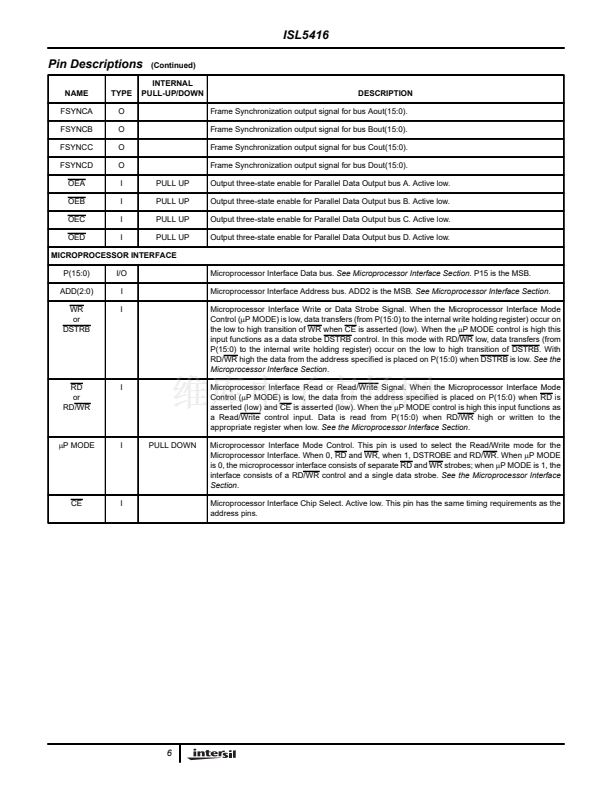
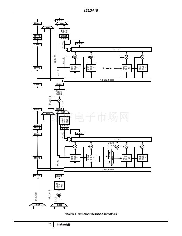
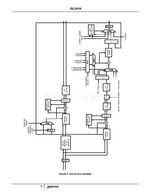
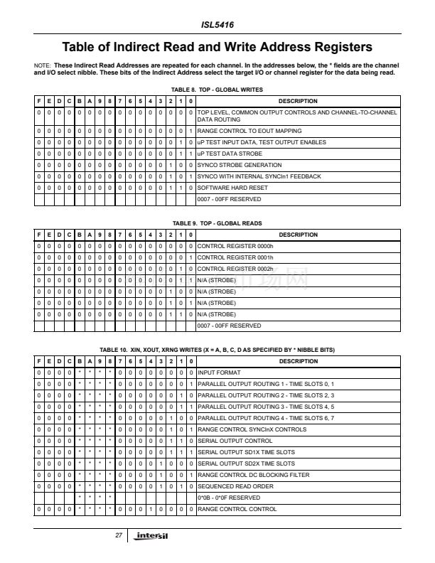
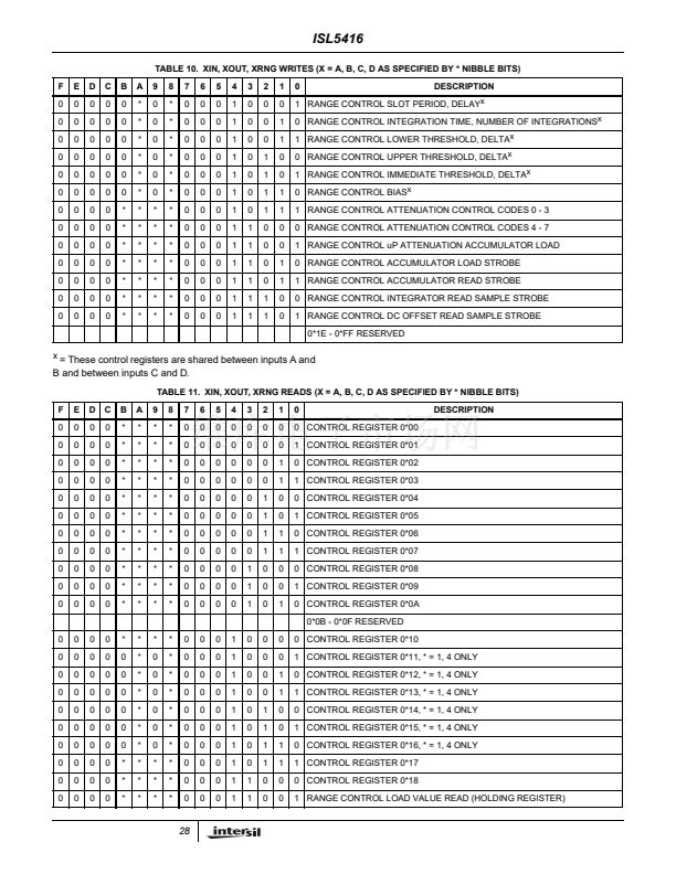
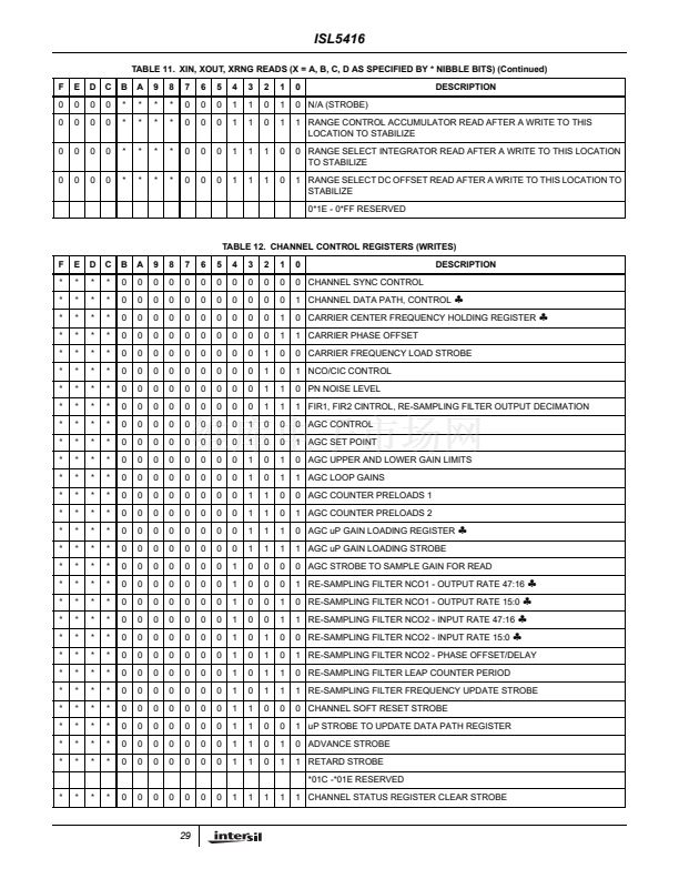
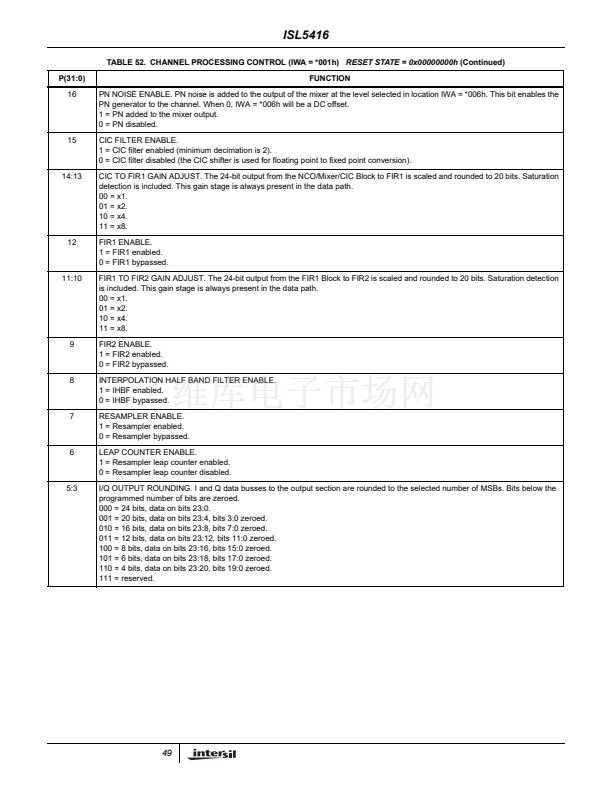
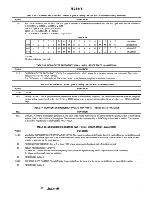
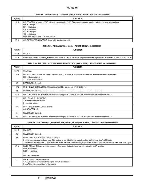
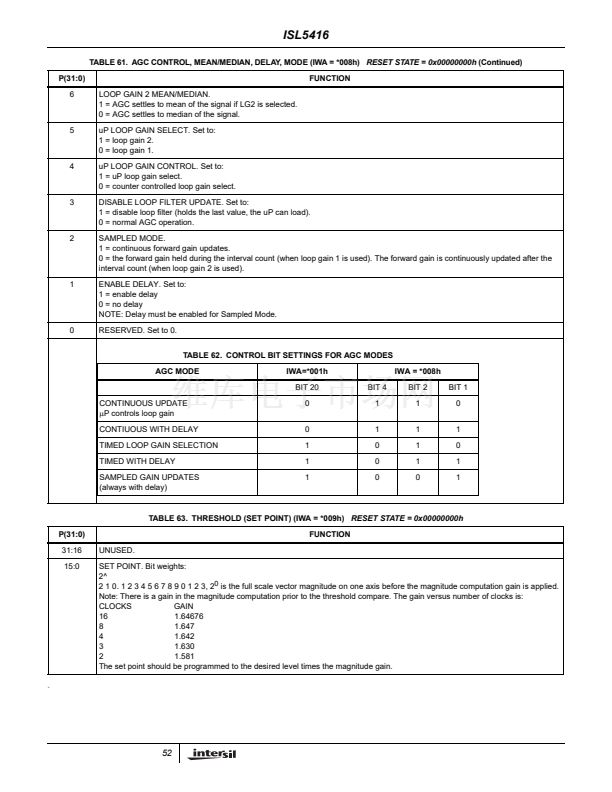
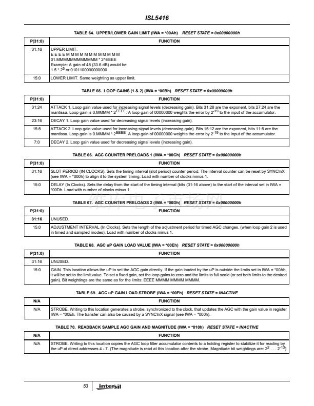
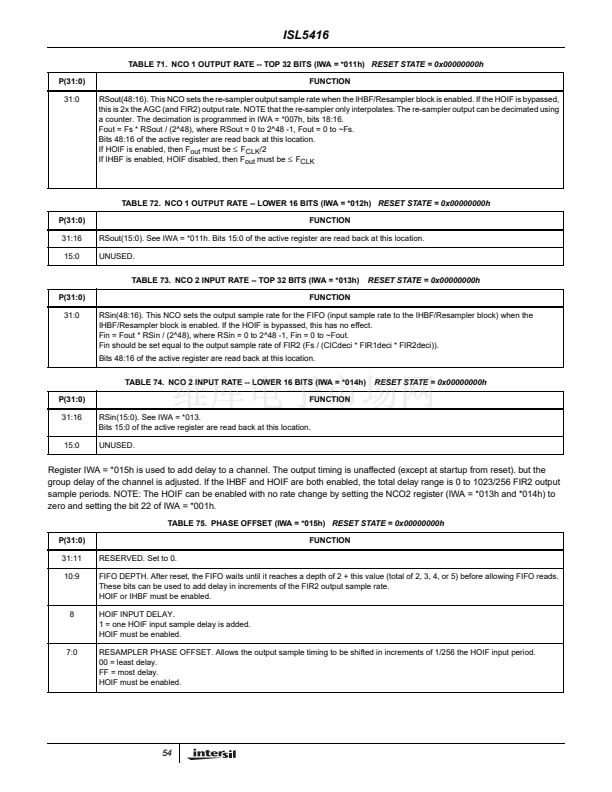
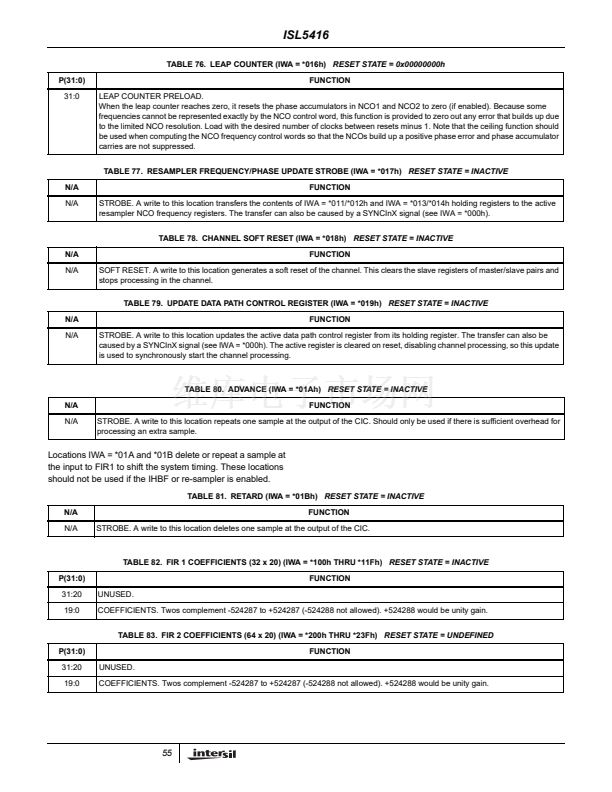
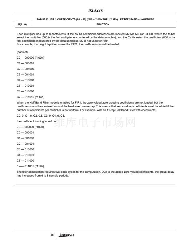
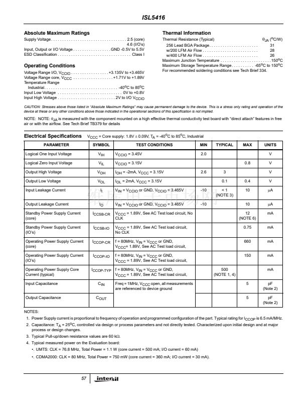
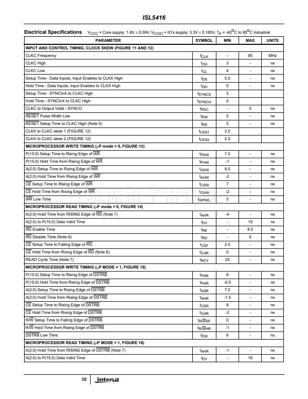
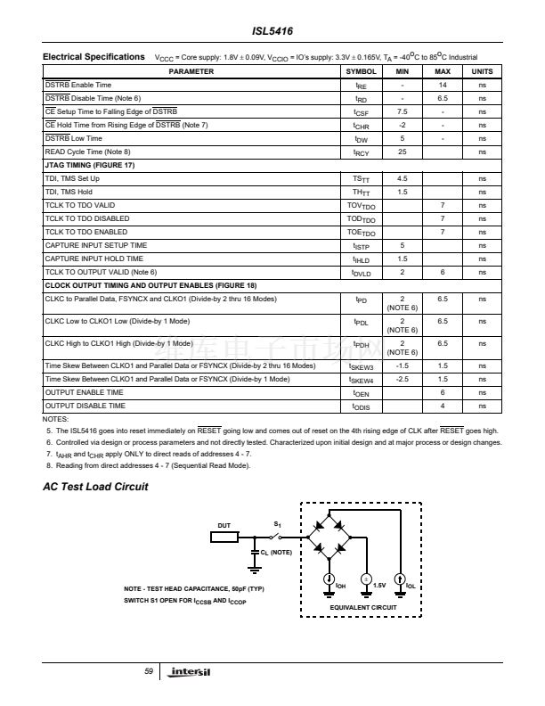
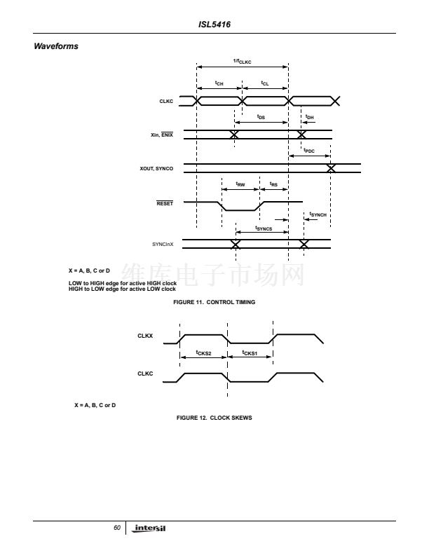
ISL5416
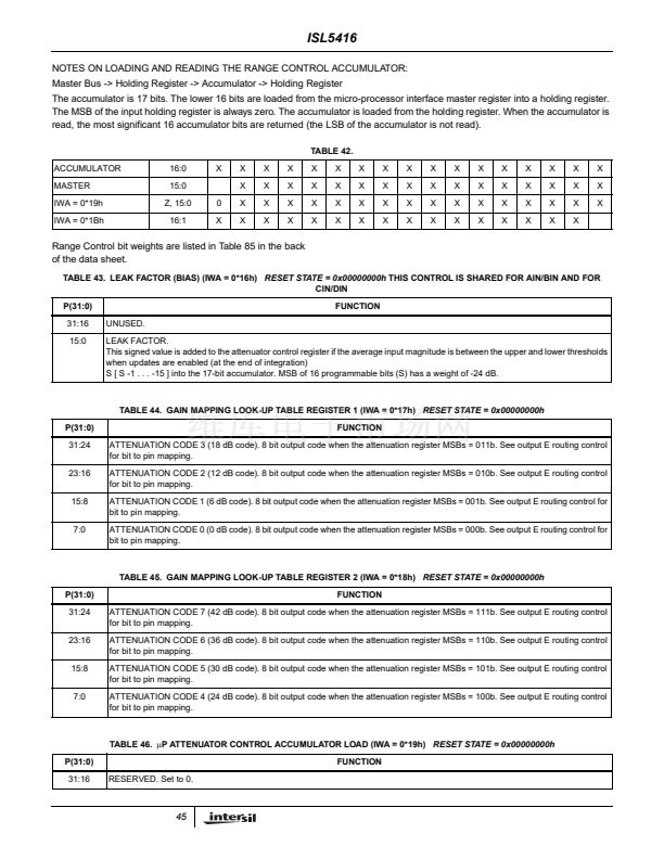
NOTES ON LOADING AND READING THE RANGE CONTROL ACCUMULATOR:
Master Bus -> Holding Register -> Accumulator -> Holding Register
The accumulator is 17 bits. The lower 16 bits are loaded from the micro-processor interface master register into a holding register.
The MSB of the input holding register is always zero. The accumulator is loaded from the holding register. When the accumulator is
read, the most significant 16 accumulator bits are returned (the LSB of the accumulator is not read).
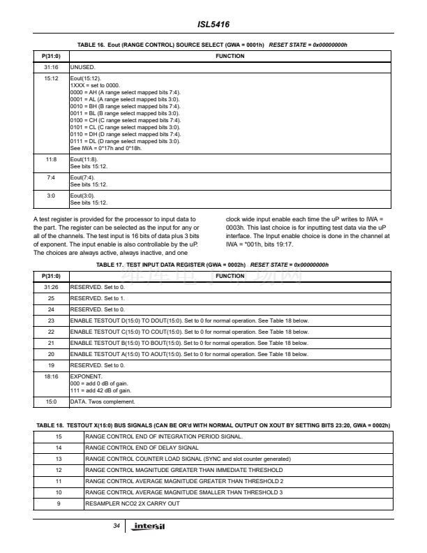
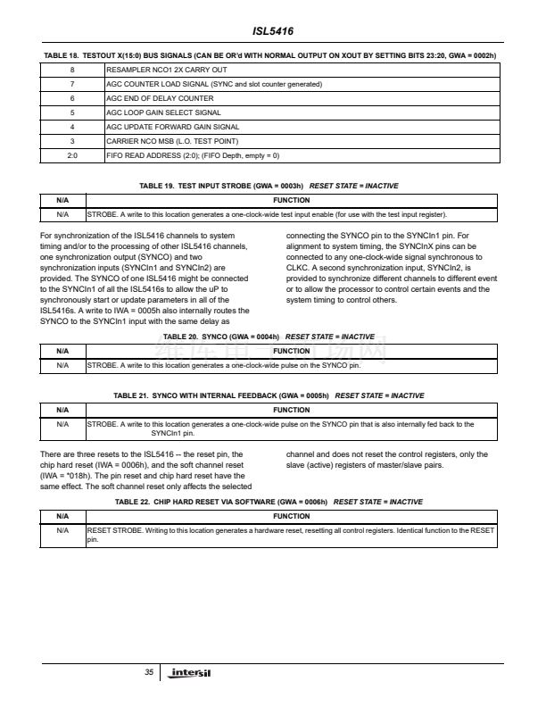
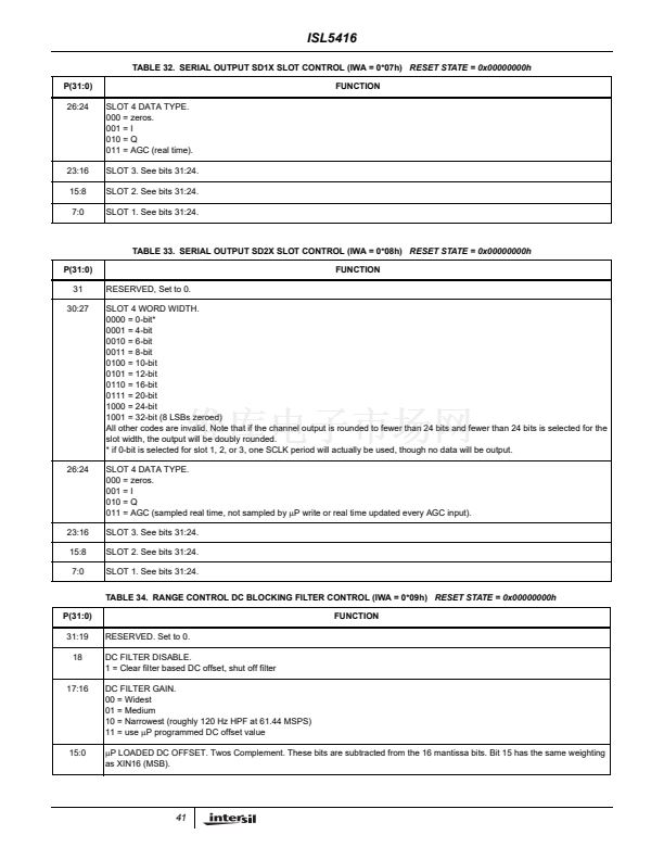
TABLE 42.
ACCUMULATOR
MASTER
IWA = 0*19h
IWA = 0*1Bh
16:0
15:0
Z, 15:0
16:1
0
X
X
X
X
X
X
X
X
X
X
X
X
X
X
X
X
X
X
X
X
X
X
X
X
X
X
X
X
X
X
X
X
X
X
X
X
X
X
X
X
X
X
X
X
X
X
X
X
X
X
X
X
X
X
X
X
X
X
X
X
X
X
X
X
X
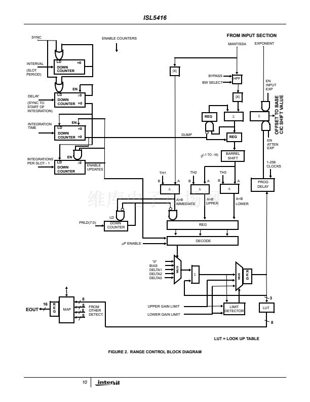
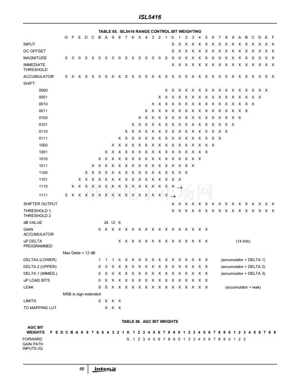
Range Control bit weights are listed in Table 85 in the back
of the data sheet.
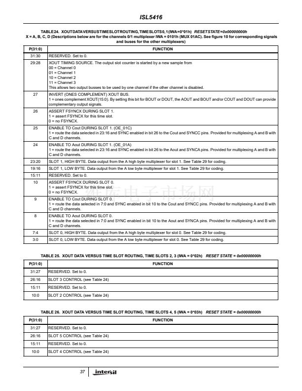
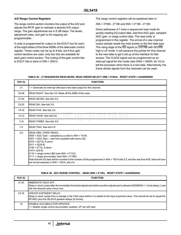
TABLE 43. LEAK FACTOR (BIAS) (IWA = 0*16h)
RESET STATE = 0x00000000h
THIS CONTROL IS SHARED FOR AIN/BIN AND FOR
CIN/DIN
P(31:0)
31:16
15:0
UNUSED.
LEAK FACTOR.
This signed value is added to the attenuator control register if the average input magnitude is between the upper and lower thresholds
when updates are enabled (at the end of integration)
S [ S -1 . . . -15 ] into the 17-bit accumulator. MSB of 16 programmable bits (S) has a weight of -24 dB.
FUNCTION
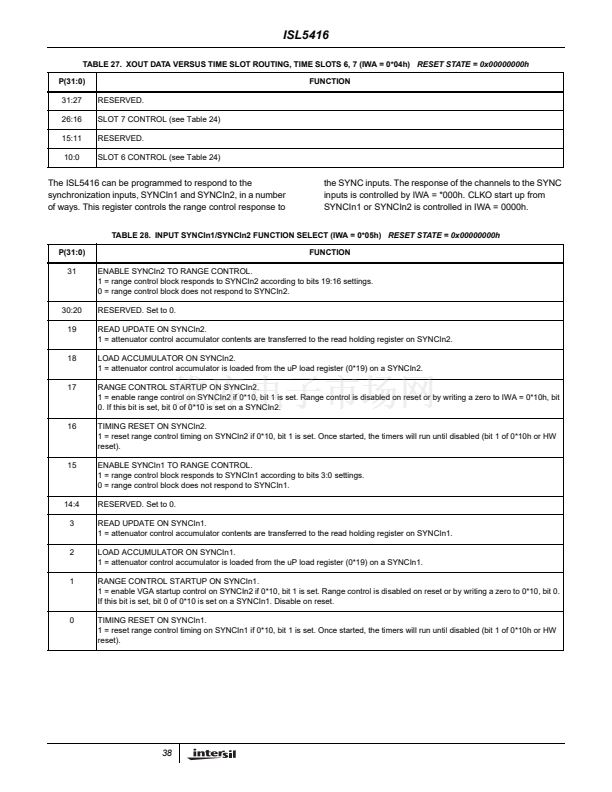
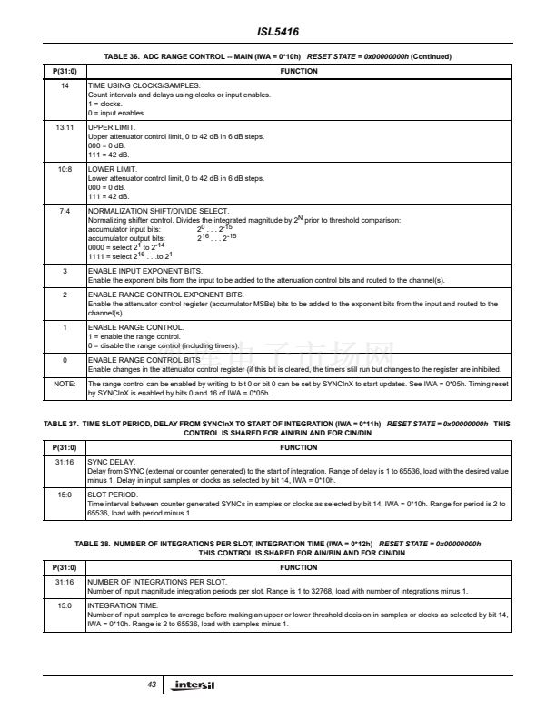
TABLE 44. GAIN MAPPING LOOK-UP TABLE REGISTER 1 (IWA = 0*17h)
RESET STATE = 0x00000000h
P(31:0)
31:24
23:16
15:8
7:0
FUNCTION
ATTENUATION CODE 3 (18 dB code). 8 bit output code when the attenuation register MSBs = 011b. See output E routing control
for bit to pin mapping.
ATTENUATION CODE 2 (12 dB code). 8 bit output code when the attenuation register MSBs = 010b. See output E routing control
for bit to pin mapping.
ATTENUATION CODE 1 (6 dB code). 8 bit output code when the attenuation register MSBs = 001b. See output E routing control for
bit to pin mapping.
ATTENUATION CODE 0 (0 dB code). 8 bit output code when the attenuation register MSBs = 000b. See output E routing control for
bit to pin mapping.
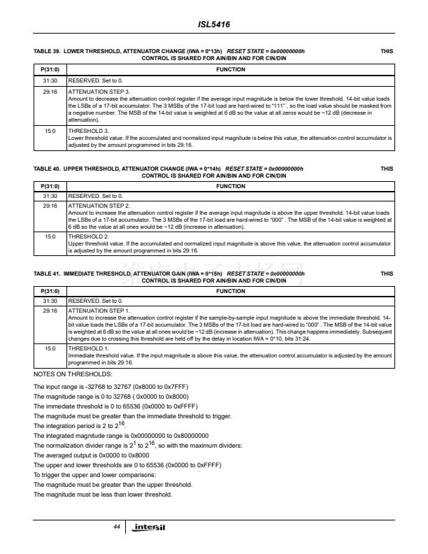
TABLE 45. GAIN MAPPING LOOK-UP TABLE REGISTER 2 (IWA = 0*18h)
RESET STATE = 0x00000000h
P(31:0)
31:24
23:16
15:8
7:0
FUNCTION
ATTENUATION CODE 7 (42 dB code). 8 bit output code when the attenuation register MSBs = 111b. See output E routing control
for bit to pin mapping.
ATTENUATION CODE 6 (36 dB code). 8 bit output code when the attenuation register MSBs = 110b. See output E routing control
for bit to pin mapping.
ATTENUATION CODE 5 (30 dB code). 8 bit output code when the attenuation register MSBs = 101b. See output E routing control
for bit to pin mapping.
ATTENUATION CODE 4 (24 dB code). 8 bit output code when the attenuation register MSBs = 100b. See output E routing control
for bit to pin mapping.
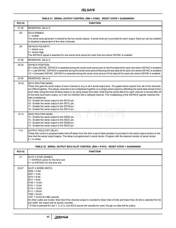
TABLE 46.
碌P
ATTENUATOR CONTROL ACCUMULATOR LOAD (IWA = 0*19h)
RESET STATE = 0x00000000h
P(31:0)
31:16
RESERVED. Set to 0.
FUNCTION
45


 1
1
 2
2
 3
3
 4
4
 5
5
 6
6
 7
7
 8
8
 9
9
 10
10
 11
11
 12
12
 13
13
 14
14
 15
15
 16
16
 17
17
 18
18
 19
19
 20
20
 21
21
 22
22
 23
23
 24
24
 25
25
 26
26
 27
27
 28
28
 29
29
 30
30
 31
31
 32
32
 33
33
 34
34
 35
35
 36
36
 37
37
 38
38
 39
39
 40
40
 41
41
 42
42
 43
43
 44
44
 45
45
 46
46
 47
47
 48
48
 49
49
 50
50
 51
51
 52
52
 53
53
 54
54
 55
55
 56
56
 57
57
 58
58
 59
59
 60
60
 61
61
 62
62
 63
63
 64
64
 65
65
 66
66
 67
67
 68
68
 69
69
 70
70
 71
71
