ISL5416
TABLE 51. CHANNEL RESET/SYNCIn1, SYNCIn2 CONTROL (IWA = *000h)
RESET STATE = 0x00000000h
(Continued)
P(31:0)
2
1
FUNCTION
AGC GAIN LOAD. Update/load AGC gain from the master/holding register to the slave/active
register on SYNCIn1.
CARRIER CENTER FREQUENCY UPDATE. Updates Carrier Center Frequency from the master/holding register to the
slave/active register on SYNCIn1.
0
DATA PATH UPDATE. Update channel processing control register (*001) on SYNCIn1.
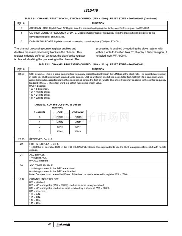
The channel processing control register enables and
disables the major processing blocks in the channel. This
register is double buffered. On reset, the slave/active register
is cleared, disabling the processing in the channel. The
processing is enabled by updating the slave register with
either a write to location IWA *019h or by a SYNCIn signal, if
enabled (see IWA *000h).
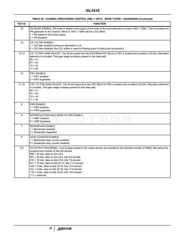
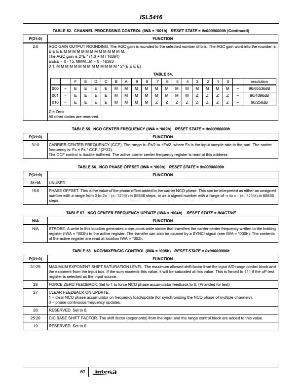
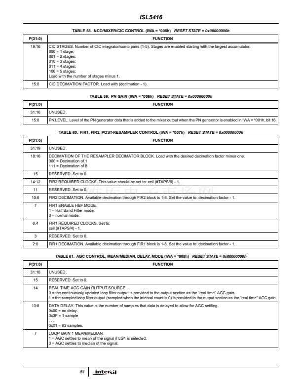
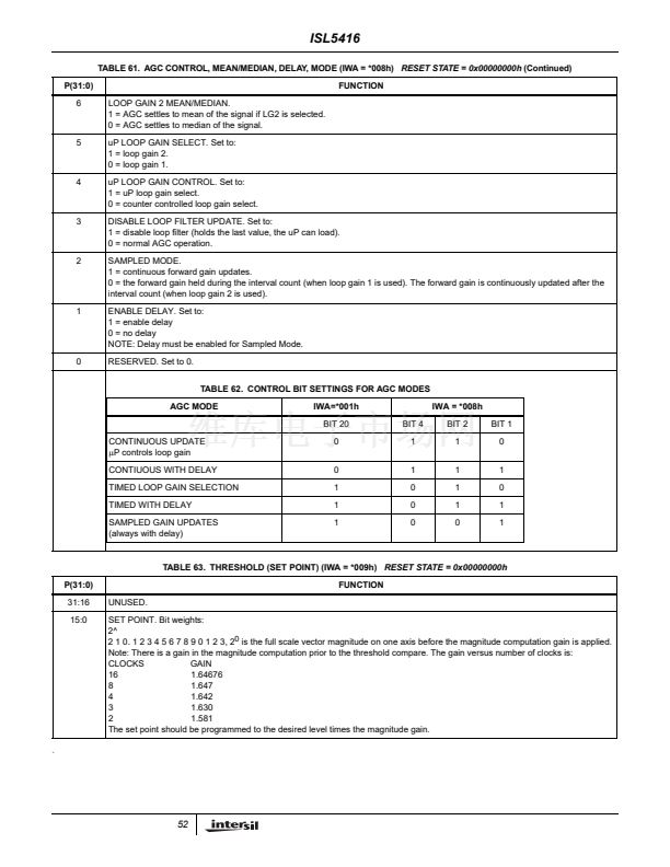
TABLE 52. CHANNEL PROCESSING CONTROL (IWA = *001h)
RESET STATE = 0x00000000h
P(31:0)
31:29
FUNCTION
COF ENABLE. This is a serial carrier offser frequency control loaded through the DIN bus at the clock rate. The serial bits are shown
in table 53. MSB justified with unused LSBs zeroed. COF is shifted in one bit per clock, MSB first. COFSYNC is one-clock-wide,
active high pulse, asserted during the clock period before the first bit (MSB). The offset frequency is added to the center frequency
loaded by the
碌P.
The offset word is a 32-bit twos complement value.
0XX = disabled.
100 = 8 bits offset.
101 = 16 bits offset.
110 = 24 bits offset.
111 = 32 bits offset.
TABLE 53. COF and COFSYNC to DIN BIT
MAPPING
CHANNEL
0
1
2
3
28:23
22
RESERVED. Set to 0.
HOIF INTERPOLATE BY 1.
1 = Set this bit to enable HOIF in the IHBF/RESAMPLER block. This is provided to use the HOIF as a phase (time) shift with no rate
change.
AGC BYPASS.
1 = bypass AGC;
0 = AGC enabled.
AGC TIMER ENABLE.
1 = timing counters in the AGC are enabled.
0 = timing counters in the AGC are disabled.
Note: Counters must be enabled if one of the timed modes is selected in register IWA = *008h.
CHANNEL INPUT SELECT.
000 = disabled.
001 = uP test register (IWA = 0002h) used as an input, always enabled.
010 = uP test register used as an input, enabled by a strobe at IWA = 0003h.
011 = reserved.
100 = AIN.
101 = BIN.
110 = CIN.
111 = DIN.
COF
DIN16
DIN12
DIN8
DIN4
COFSYNC
DIN15
DIN11
DIN7
DIN3
21
20
19:17
48


 1
1
 2
2
 3
3
 4
4
 5
5
 6
6
 7
7
 8
8
 9
9
 10
10
 11
11
 12
12
 13
13
 14
14
 15
15
 16
16
 17
17
 18
18
 19
19
 20
20
 21
21
 22
22
 23
23
 24
24
 25
25
 26
26
 27
27
 28
28
 29
29
 30
30
 31
31
 32
32
 33
33
 34
34
 35
35
 36
36
 37
37
 38
38
 39
39
 40
40
 41
41
 42
42
 43
43
 44
44
 45
45
 46
46
 47
47
 48
48
 49
49
 50
50
 51
51
 52
52
 53
53
 54
54
 55
55
 56
56
 57
57
 58
58
 59
59
 60
60
 61
61
 62
62
 63
63
 64
64
 65
65
 66
66
 67
67
 68
68
 69
69
 70
70
 71
71
