ADIS16201
YINCL_SCALE Register Definition
Address
0x1F, 0x1E
1
Scale
1
0.0488%
Default
0x0800
Format
Binary
Access
R/W
Scale is the weight of each LSB.
The YINCL_SCALE register is the user-controlled register for
calibrating system-level inclination sensitivity errors. For the
Y-axis inclination, it represents the A variable in the calibration
equation. The calibration range is from 0 to 2, or 0 to 4095 codes,
assuming nominal sensor sensitivity. The contents of this register
are nonvolatile.
Table 18. YINCL_SCALE Bit Designations
Bit
15:12
11:0
Description
Not used
Data bits
Note that when enabled, the hardware output indicator serves
both the Alarm 1 and Alarm 2 functions and cannot be used to
differentiate between one alarm condition and the other. It is
simply used to indicate that an alarm is active and that the user
should poll the device via the SPI to determine the source of the
alarm condition (see the STATUS Register Definition section).
Because the ALM_CTRL, MSC_CTRL, and GPIO_CTRL
control registers can influence the same GPIO pins, a priority
level has been established to avoid conflicting assignments of
the two GPIO pins. This priority level is defined as
MSC_CTRL, which has precedence over ALM_CTRL, which
has precedence over GPIO_CTRL.
The ALM_MAG1 control register used in controlling the
Alarm 1 function has two roles. The first role is to store the
value with which the output data variable is compared to
discern if an alarm condition exists or not. The second role is to
identify whether the alarm should be active for excursions
above or below the alarm limit. If 1 is written to the GT1 bit of
the ALM_MAG1 control register, the alarm is active for
excursions extending above a given limit. If 0 is written to the
GT1 bit, the alarm is active for excursions dropping below the
given limit. The comparison value contained within the
ALM_MAG1 control register is located within the lower 14 bits.
The format utilized for this 14-bit value should match that of
the output data register that is being monitored for the alarm
condition. For instance, if the YINCL_OUT output data register
is being monitored by Alarm 1, then the 14-bit value within the
ALM_MAG1 control register takes on a twos complement
format with each LSB equating to nominal 0.1掳 (assumes unity
scale and zero offset factors). The ALM_MAG value is
compared against the instantaneous value of the parameter
being monitored.
Use caution when monitoring the temperature output register
for the alarm conditions. Here, the negative temperature scale
factor results in the greater than and less than selections
requiring reverse logic.
When the THR function is enabled, the output data variable is
compared against the ALM_MAG1 level. When the ROC
function is enabled, the comparison of the output data variable
is against the ALM_MAG1 level averaged over the number of
samples, as identified in the ALM_SMPL1 control register. This
acts to create a comparison of (螖 units/螖 time) or the derivative
of the output data variable against a predefined slope.
ALARMS
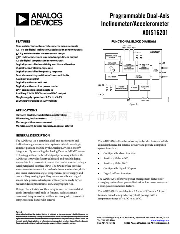
The ADIS16201 contains two independent alarm functions that are
referred to as Alarm 1 and Alarm 2. The Alarm 1 function is
managed by the ALM_MAG1 and ALM_SMPL1 control registers.
The Alarm 2 function is managed by the ALM_MAG2 and
ALM_SMPL2 control registers. Both the Alarm 1 and Alarm 2
functions share the ALM_CTRL register. For simplicity, the
following text references the Alarm 1 functionality only.
The 16-bit ALM_CTRL register serves three distinct roles in
controlling the Alarm 1 function. First, it is used to enable the
overall Alarm 1 function and select the output data variable that
is to be monitored for the alarm condition. Second, it is used to
select whether the Alarm 1 function is based upon a predefined
threshold (THR) level or a predefined rate-of-change (ROC)
slope. Third, the ALM_CTRL register can be used in setting up
one of the two general-purpose input/output lines (GPIOs) to
serve as a hardware output that indicates when an alarm
condition has occurred. Enabling the I/O alarm function,
setting its polarity, and controlling its operation are
accomplished using this register.
Rev. A | Page 21 of 32


 1
1
 2
2
 3
3
 4
4
 5
5
 6
6
 7
7
 8
8
 9
9
 10
10
 11
11
 12
12
 13
13
 14
14
 15
15
 16
16
 17
17
 18
18
 19
19
 20
20
 21
21
 22
22
 23
23
 24
24
 25
25
 26
26
 27
27
 28
28
 29
29
 30
30
 31
31
 32
32
