W79E532/W79L532
+
-
+
-
+
-
+
-
+
-
+
-
PWM5OE
PWM4OE
PWM3OE
PWM2OE
PWM1OE
PWM0 Register
PWM0 Buffer
overflow
PWM0OE
PWM0
P1.0
Fosc
1/2
PWMP
ENPWM0
PWM1 Register
8-bit Up Counter
PWM1 Buffer
overflow
ENPWM1
8-bit Up Counter
PWM1
P1.1
PWM2 Register
PWM2 Buffer
overflow
ENPWM2
8-bit Up Counter
PWM2
P1.2
PWM3 Register
PWM3 Buffer
overflow
ENPWM3
8-bit Up Counter
PWM3
P1.3
PWM4 Register
PWM4 Buffer
overflow
ENPWM4
8-bit Up Counter
PWM4
P1.4
PWM5 Register
PWM5 Buffer
overflow
ENPWM5
8-bit Up Counter
PWM5
P1.5
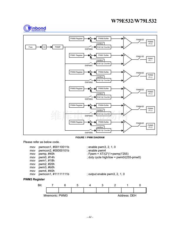
FIGURE 1 PWM DIAGRAM
Please refer as below code.
mov
mov
mov
mov
mov
mov
mov
mov
mov
pwmcon1, #00110011b
pwmcon2, #00000101b
pwmp, #40h
pwm0, #14h
pwm1, #18h
pwm2, #20h
pwm3, #b0h
pwm4, #40h
pwmcon1, #11111111b
; enable pwm3, 2, 1, 0
; enable pwm4
; Fpwm = XT/(2*(1+pwmp)*255)
; duty cycle high/low = pwm0/(255-pmw0)
; output enable pwm3, 2, 1, 0
PWM3 Register
Bit:
7
6
5
4
3
2
1
0
Mnemonic: PWM3
Address: DEH
- 44 -


 1
1
 2
2
 3
3
 4
4
 5
5
 6
6
 7
7
 8
8
 9
9
 10
10
 11
11
 12
12
 13
13
 14
14
 15
15
 16
16
 17
17
 18
18
 19
19
 20
20
 21
21
 22
22
 23
23
 24
24
 25
25
 26
26
 27
27
 28
28
 29
29
 30
30
 31
31
 32
32
 33
33
 34
34
 35
35
 36
36
 37
37
 38
38
 39
39
 40
40
 41
41
 42
42
 43
43
 44
44
 45
45
 46
46
 47
47
 48
48
 49
49
 50
50
 51
51
 52
52
 53
53
 54
54
 55
55
 56
56
 57
57
 58
58
 59
59
 60
60
 61
61
 62
62
 63
63
 64
64
 65
65
 66
66
 67
67
 68
68
 69
69
 70
70
 71
71
 72
72
 73
73
 74
74
 75
75
 76
76
 77
77
