W79E532/W79L532
The TI flag is set high in C1 following the end of transmission of the last bit. The serial port will receive
data when REN is 1 and RI is zero. The shift clock (TxD) will be activated and the serial port will latch
data on the rising edge of shift clock. The external device should therefore present data on the falling
edge on the shift clock. This process continues till all the 8 bits have been received. The RI flag is set
in C1 following the last rising edge of the shift clock on TxD. This will stop reception, till the RI is
cleared by software.
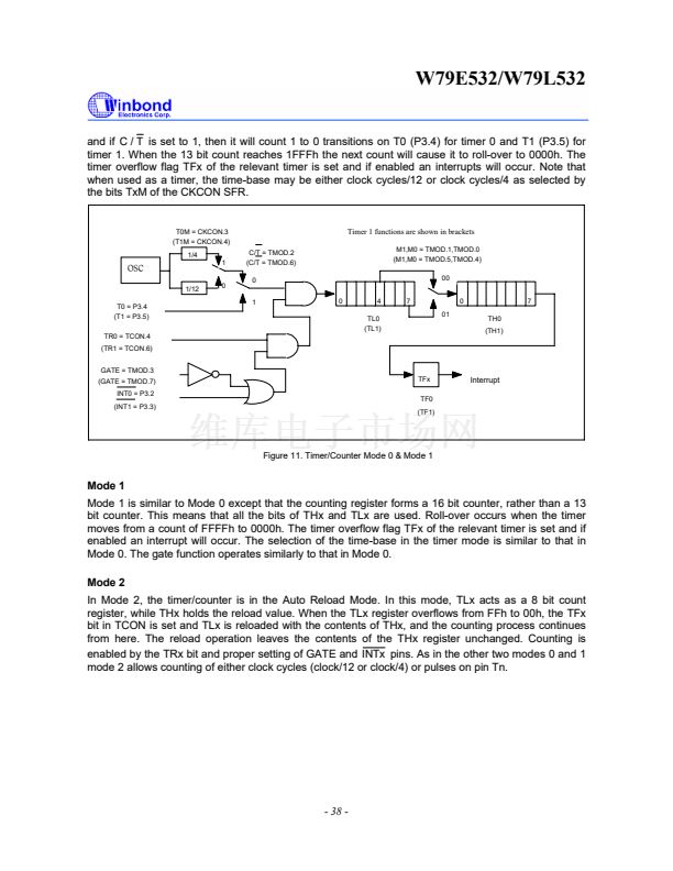
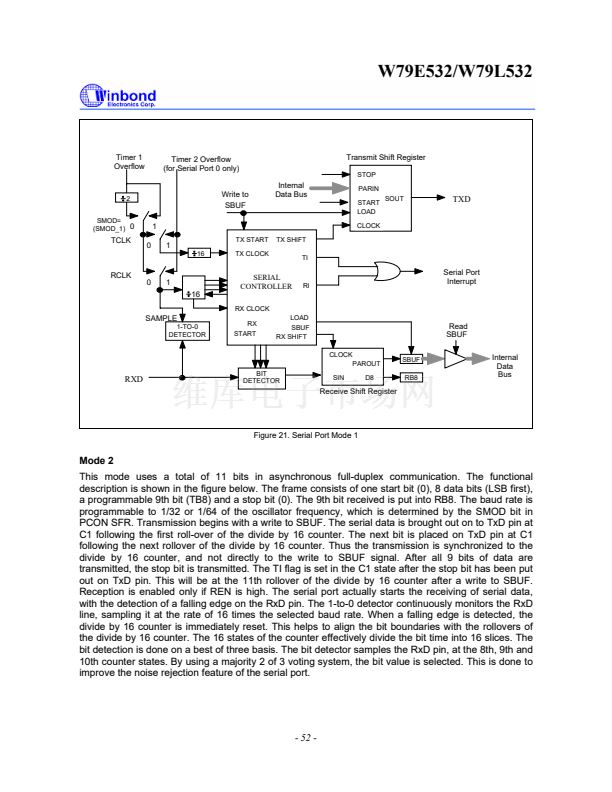
Mode 1
In Mode 1, the full duplex asynchronous mode is used. Serial communication frames are made up of
10 bits transmitted on TXD and received on RXD. The 10 bits consist of a start bit (0), 8 data bits (LSB
first), and a stop bit (1). On receive, the stop bit goes into RB8 in the SFR SCON. The baud rate in this
mode is variable. The serial baud can be programmed to be 1/16 or 1/32 of the Timer 1 overflow.
Since the Timer 1 can be set to different reload values, a wide variation in baud rates is possible.
Transmission begins with a write to SBUF. The serial data is brought out on to TxD pin at C1 following
the first roll-over of divide by 16 counter. The next bit is placed on TxD pin at C1 following the next
rollover of the divide by 16 counter. Thus the transmission is synchronized to the divide by 16 counter
and not directly to the write to SBUF signal. After all 8 bits of data are transmitted, the stop bit is
transmitted. The TI flag is set in the C1 state after the stop bit has been put out on TxD pin. This will
be at the 10th rollover of the divide by 16 counter after a write to SBUF.
Reception is enabled only if REN is high. The serial port actually starts the receiving of serial data,
with the detection of a falling edge on the RxD pin. The 1-to-0 detector continuously monitors the RxD
line, sampling it at the rate of 16 times the selected baud rate. When a falling edge is detected, the
divide by 16 counter is immediately reset. This helps to align the bit boundaries with the rollovers of
the divide by 16 counter.
The 16 states of the counter effectively divide the bit time into 16 slices. The bit detection is done on a
best of three basis. The bit detector samples the RxD pin, at the 8th, 9th and 10th counter states. By
using a majority 2 of 3 voting system, the bit value is selected. This is done to improve the noise
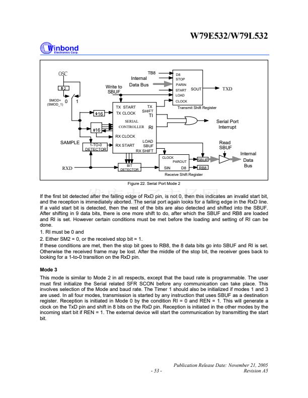
rejection feature of the serial port. If the first bit detected after the falling edge of RxD pin is not 0, then
this indicates an invalid start bit, and the reception is immediately aborted. The serial port again looks
for a falling edge in the RxD line. If a valid start bit is detected, then the rest of the bits are also
detected and shifted into the SBUF.
After shifting in 8 data bits, there is one more shift to do, after which the SBUF and RB8 are loaded
and RI is set. However certain conditions must be met before the loading and setting of RI can be
done.
1. RI must be 0 and
2. Either SM2 = 0, or the received stop bit = 1.
If these conditions are met, then the stop bit goes to RB8, the 8 data bits go into SBUF and RI is set.
Otherwise the received frame may be lost. After the middle of the stop bit, the receiver goes back to
looking for a 1-to-0 transition on the RxD pin.
- 51 -
Publication Release Date: November 21, 2005
Revision A5


 1
1
 2
2
 3
3
 4
4
 5
5
 6
6
 7
7
 8
8
 9
9
 10
10
 11
11
 12
12
 13
13
 14
14
 15
15
 16
16
 17
17
 18
18
 19
19
 20
20
 21
21
 22
22
 23
23
 24
24
 25
25
 26
26
 27
27
 28
28
 29
29
 30
30
 31
31
 32
32
 33
33
 34
34
 35
35
 36
36
 37
37
 38
38
 39
39
 40
40
 41
41
 42
42
 43
43
 44
44
 45
45
 46
46
 47
47
 48
48
 49
49
 50
50
 51
51
 52
52
 53
53
 54
54
 55
55
 56
56
 57
57
 58
58
 59
59
 60
60
 61
61
 62
62
 63
63
 64
64
 65
65
 66
66
 67
67
 68
68
 69
69
 70
70
 71
71
 72
72
 73
73
 74
74
 75
75
 76
76
 77
77
