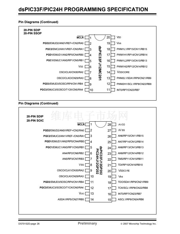
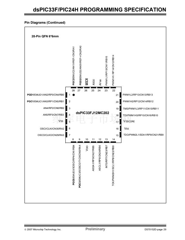
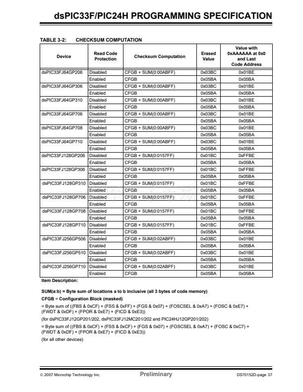
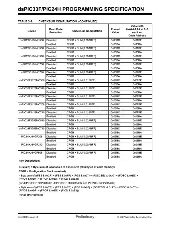
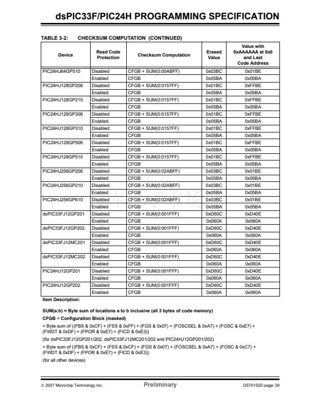
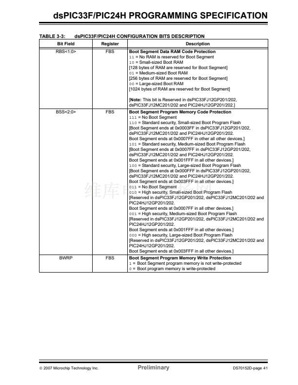
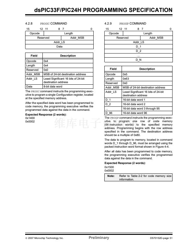
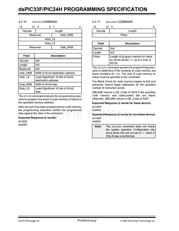
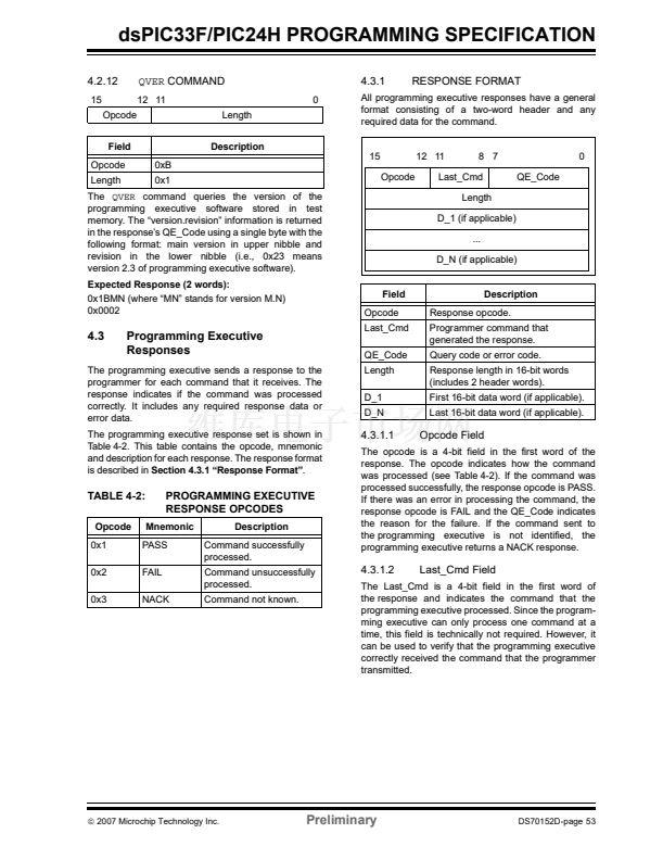
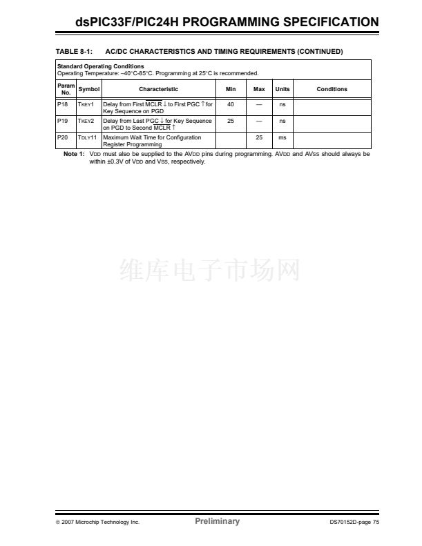
HIGH-LEVEL ICSP鈩?/div>
PROGRAMMING FLOW
Start
ICSP mode is a special programming protocol that
allows you to read and write to dsPIC33F/PIC24H
device family memory. The ICSP mode is the most
direct method used to program the device; note, how-
ever, that Enhanced ICSP is faster. ICSP mode also
has the ability to read the contents of executive mem-
ory to determine if the programming executive is
present. This capability is accomplished by applying
control codes and instructions serially to the device
using pins PGC and PGD.
In ICSP mode, the system clock is taken from the PGC
pin, regardless of the device鈥檚 oscillator Configuration
bits. All instructions are shifted serially into an internal
buffer, then loaded into the instruction register and
executed. No program fetching occurs from internal
memory. Instructions are fed in 24 bits at a time. PGD
is used to shift data in, and PGC is used as both the
serial shift clock and the CPU execution clock.
Note:
During ICSP operation, the operating
frequency of PGC must not exceed
5 MHz.
Enter ICSP鈩?/div>
Perform Bulk
Erase
Program Memory
Verify Program
Program Configuration Bits
Verify Configuration Bits
Exit ICSP
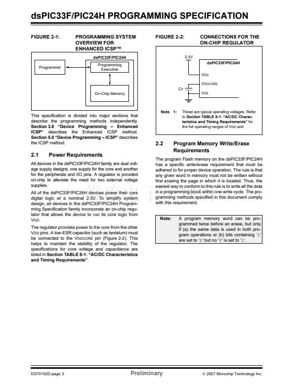
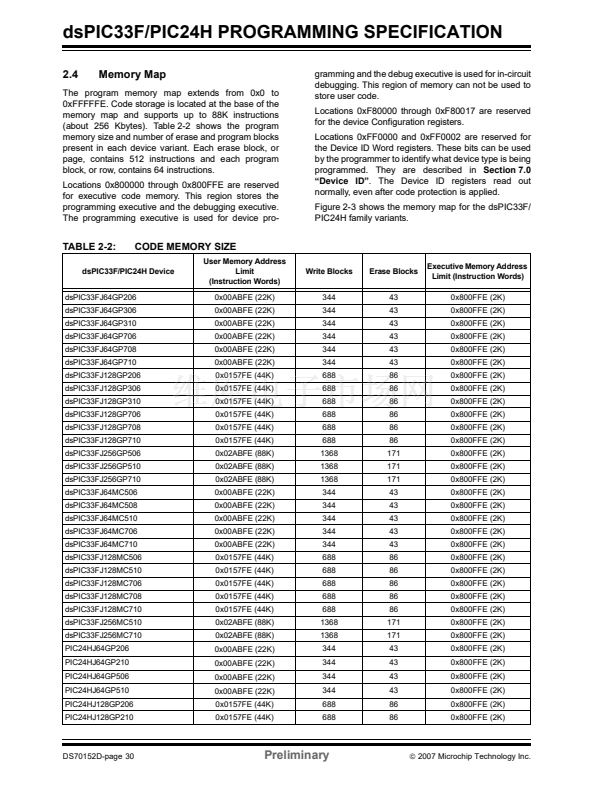
5.1
Overview of the Programming
Process
5.2
Done
Figure 5-1 shows the high-level overview of the
programming process. After entering ICSP mode, the
first action is to Bulk Erase the device. Next, the code
memory is programmed, followed by the device Con-
figuration registers. Code memory (including the
Configuration registers) is then verified to ensure that
programming was successful. Then, program the
code-protect Configuration bits, if required.
ICSP Operation
Upon entry into ICSP mode, the CPU is Idle. Execution
of the CPU is governed by an internal state machine. A
4-bit control code is clocked in using PGC and PGD and
this control code is used to command the CPU (see
Table 5-1).
The SIX control code is used to send instructions to the
CPU for execution and the REGOUT control code is
used to read data out of the device via the VISI register.
TABLE 5-1:
CPU CONTROL CODES IN
ICSP鈩?MODE
Description
Shift in 24-bit instruction
and execute.
Shift out the VISI
register.
Reserved.
4-Bit
Mnemonic
Control Code
0000b
0001b
0010b-1111b
SIX
REGOUT
N/A
漏
2007 Microchip Technology Inc.
Preliminary
DS70152D-page 55


 1
1
 2
2
 3
3
 4
4
 5
5
 6
6
 7
7
 8
8
 9
9
 10
10
 11
11
 12
12
 13
13
 14
14
 15
15
 16
16
 17
17
 18
18
 19
19
 20
20
 21
21
 22
22
 23
23
 24
24
 25
25
 26
26
 27
27
 28
28
 29
29
 30
30
 31
31
 32
32
 33
33
 34
34
 35
35
 36
36
 37
37
 38
38
 39
39
 40
40
 41
41
 42
42
 43
43
 44
44
 45
45
 46
46
 47
47
 48
48
 49
49
 50
50
 51
51
 52
52
 53
53
 54
54
 55
55
 56
56
 57
57
 58
58
 59
59
 60
60
 61
61
 62
62
 63
63
 64
64
 65
65
 66
66
 67
67
 68
68
 69
69
 70
70
 71
71
 72
72
 73
73
 74
74
 75
75
 76
76
 77
77
 78
78
 79
79
 80
80
