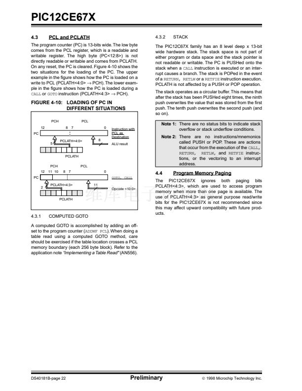
PCH). The lower exam-
鈫?/div>
PCH).
The PIC12C67X family has an 8 level deep x 13-bit
wide hardware stack. The stack space is not part of
either program or data space and the stack pointer is
not readable or writable. The PC is PUSHed onto the
stack when a
CALL
instruction is executed or an inter-
rupt causes a branch. The stack is POPed in the event
of a
RETURN, RETLW
or a
RETFIE
instruction execution.
PCLATH is not affected by a PUSH or POP operation.
The stack operates as a circular buffer. This means that
after the stack has been PUSHed eight times, the ninth
push overwrites the value that was stored from the 铿乺st
push. The tenth push overwrites the second push (and
so on).
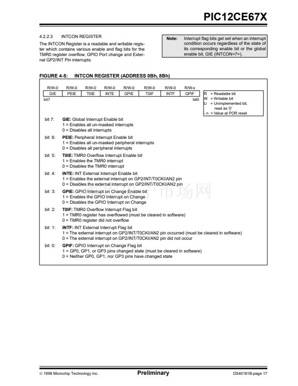
Note 1:
There are no status bits to indicate stack
over铿俹w or stack under铿俹w conditions.
Note 2:
There are no instructions/mnemonics
called PUSH or POP. These are actions
that occur from the execution of the
CALL,
RETURN, RETLW,
and
RETFIE
instruc-
tions, or the vectoring to an interrupt
address.
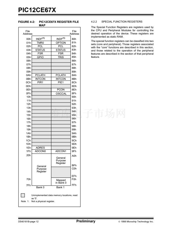
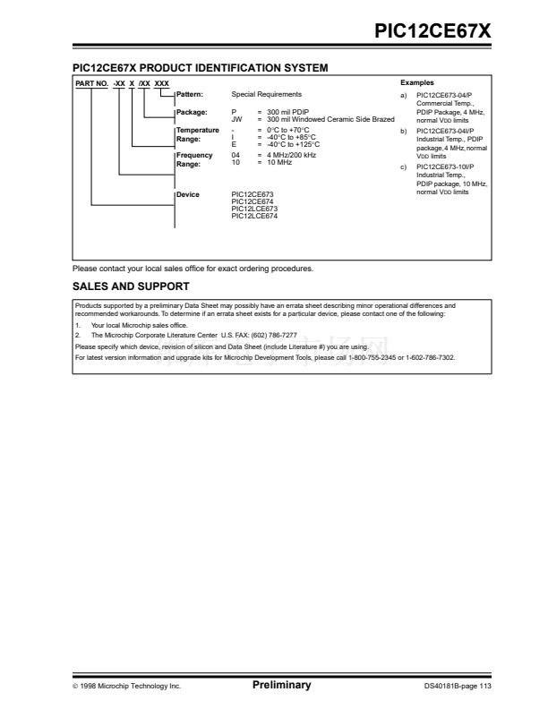
FIGURE 4-10: LOADING OF PC IN
DIFFERENT SITUATIONS
PCH
12
PC
5
PCLATH<4:0>
8
8
7
PCL
0
Instruction with
PCL as
Destination
ALU result
PCLATH
PCH
12
PC
2
PCLATH<4:3>
11
Opcode <10:0>
PCLATH
11 10
8
7
PCL
0
GOTO, CALL
4.4
Program Memory Paging
4.3.1
COMPUTED GOTO
The PIC12CE67X ignores both paging bits
PCLATH<4:3>, which are used to access program
memory when more than one page is available. The
use of PCLATH<4:3> as general purpose read/write
bits for the PIC12CE67X is not recommended since
this may affect upward compatibility with future prod-
ucts.
A computed GOTO is accomplished by adding an off-
set to the program counter (ADDWF
PCL).
When doing a
table read using a computed GOTO method, care
should be exercised if the table location crosses a PCL
memory boundary (each 256 byte block). Refer to the
application note
鈥淚mplementing a Table Read"
(AN556).
DS40181B-page 22
Preliminary
漏
1998 Microchip Technology Inc.


 1
1
 2
2
 3
3
 4
4
 5
5
 6
6
 7
7
 8
8
 9
9
 10
10
 11
11
 12
12
 13
13
 14
14
 15
15
 16
16
 17
17
 18
18
 19
19
 20
20
 21
21
 22
22
 23
23
 24
24
 25
25
 26
26
 27
27
 28
28
 29
29
 30
30
 31
31
 32
32
 33
33
 34
34
 35
35
 36
36
 37
37
 38
38
 39
39
 40
40
 41
41
 42
42
 43
43
 44
44
 45
45
 46
46
 47
47
 48
48
 49
49
 50
50
 51
51
 52
52
 53
53
 54
54
 55
55
 56
56
 57
57
 58
58
 59
59
 60
60
 61
61
 62
62
 63
63
 64
64
 65
65
 66
66
 67
67
 68
68
 69
69
 70
70
 71
71
 72
72
 73
73
 74
74
 75
75
 76
76
 77
77
 78
78
 79
79
 80
80
 81
81
 82
82
 83
83
 84
84
 85
85
 86
86
 87
87
 88
88
 89
89
 90
90
 91
91
 92
92
 93
93
 94
94
 95
95
 96
96
 97
97
 98
98
 99
99
 100
100
 101
101
 102
102
 103
103
 104
104
 105
105
 106
106
 107
107
 108
108
 109
109
 110
110
 111
111
 112
112
 113
113
 114
114
 115
115
 116
116
