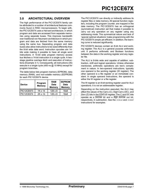
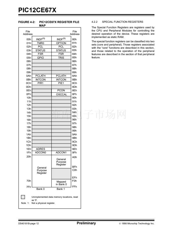
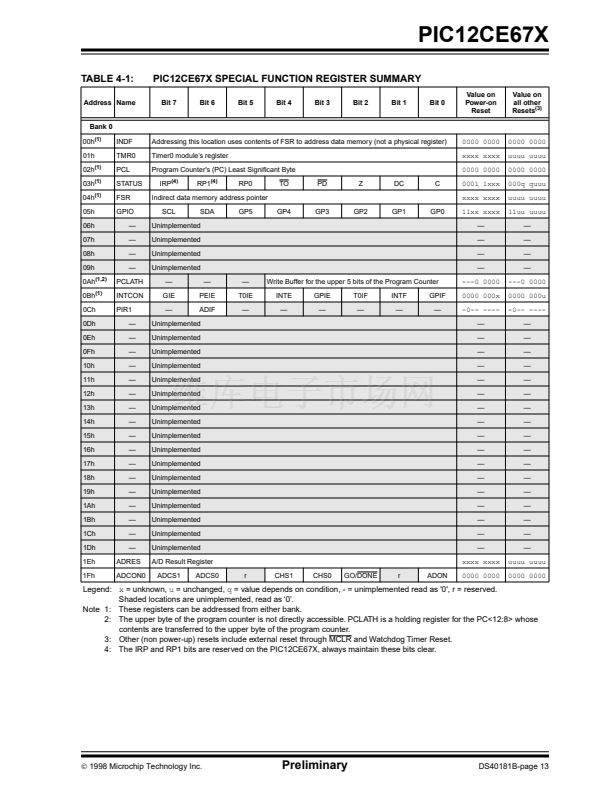
PIC12CE67X
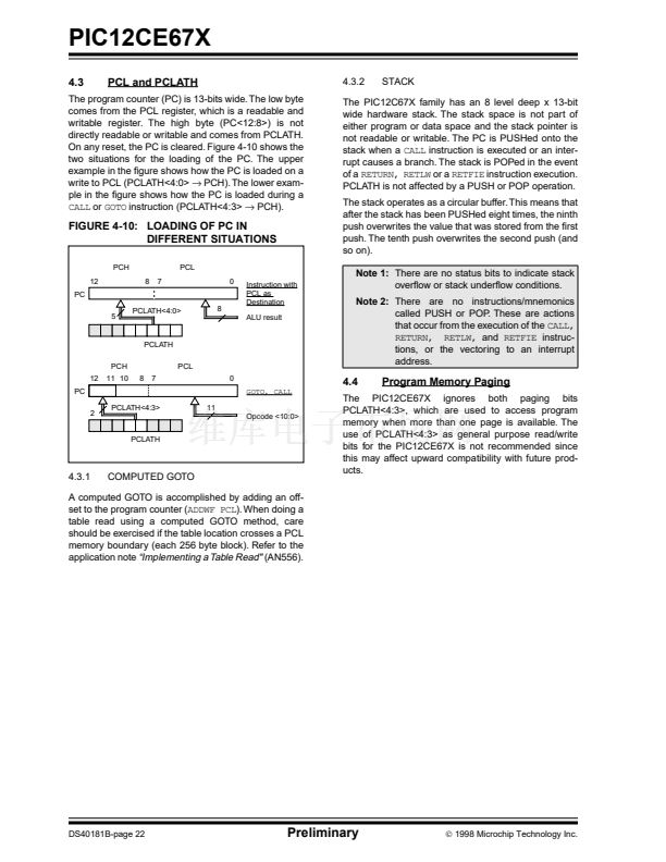
9.4
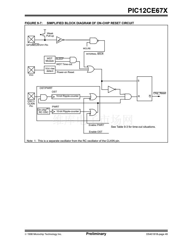
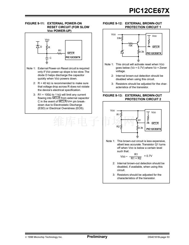
Power-on Reset (POR), Power-up
Timer (PWRT) and Oscillator Start-up
Timer (OST)
POWER-ON RESET (POR)
9.4.3
OSCILLATOR START-UP TIMER (OST)
The Oscillator Start-up Timer (OST) provides 1024
oscillator cycle (from OSC1 input) delay after the
PWRT delay is over. This ensures that the crystal oscil-
lator or resonator has started and stabilized.
The OST time-out is invoked only for XT, LP and HS
modes and only on Power-on Reset or wake-up from
SLEEP.
9.4.4
TIME-OUT SEQUENCE
9.4.1
The on-chip POR circuit holds the chip in reset until
V
DD
has reached a high enough level for proper opera-
tion. To take advantage of the POR, just tie the MCLR
pin through a resistor to V
DD
. This will eliminate exter-
nal RC components usually needed to create a Power-
on Reset. A maximum rise time for V
DD
is speci铿乪d.
See Electrical Speci铿乧ations for details.
When the device starts normal operation (exits the
reset condition), device operating parameters (voltage,
frequency, temperature, ...) must be met to ensure
operation. If these conditions are not met, the device
must be held in reset until the operating conditions are
met.
For additional information, refer to Application Note
AN607, "Power-up
Trouble Shooting."
9.4.2
POWER-UP TIMER (PWRT)
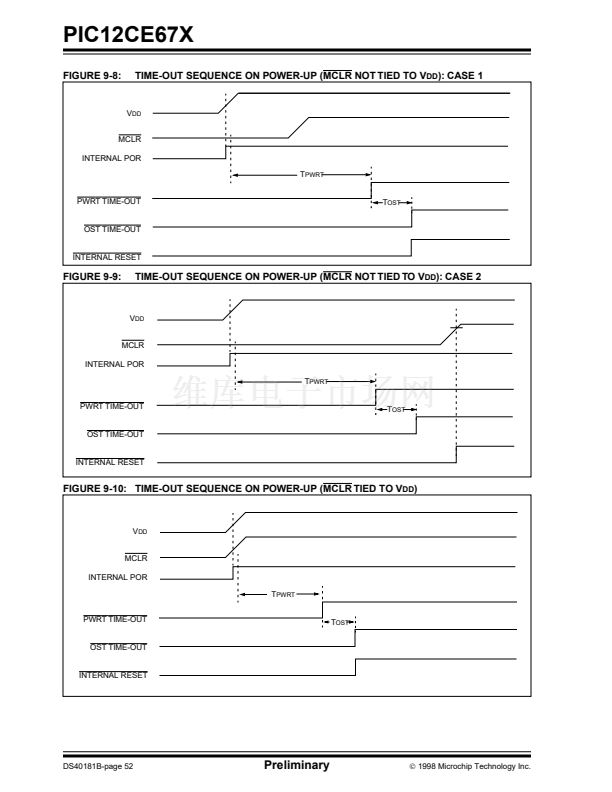
On power-up the time-out sequence is as follows: First
PWRT time-out is invoked after the POR time delay has
expired. Then OST is activated. The total time-out will
vary based on oscillator con铿乬uration and the status of
the PWRT. For example, in RC mode with the PWRT
disabled, there will be no time-out at all. Figure 9-8,
Figure 9-9, and Figure 9-10 depict time-out sequences
on power-up.
Since the time-outs occur from the POR pulse, if MCLR
is kept low long enough, the time-outs will expire. Then
bringing MCLR high will begin execution immediately
(Figure 9-9). This is useful for testing purposes or to
synchronize more than one PIC12CE67X device oper-
ating in parallel.
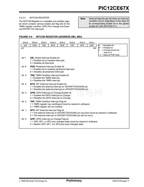
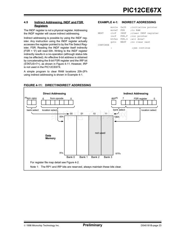
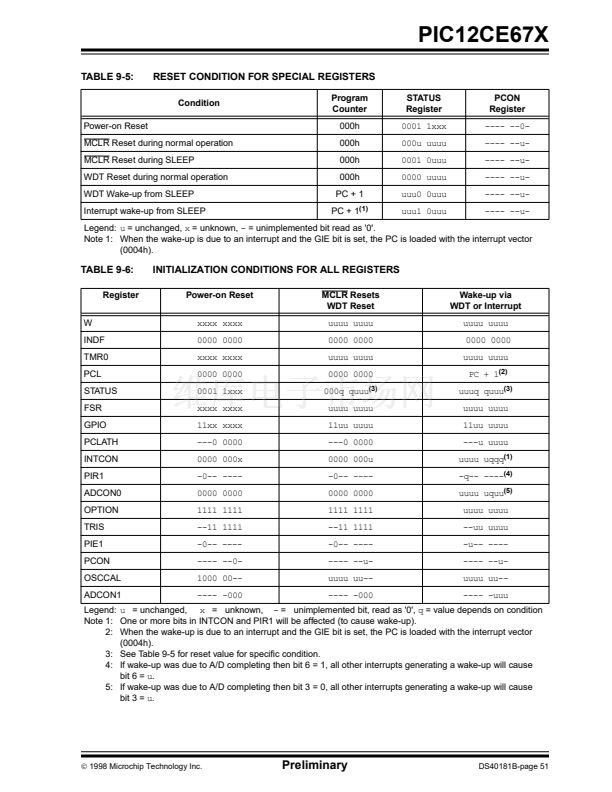
Table 9-5 shows the reset conditions for all the regis-
ters.
9.4.5
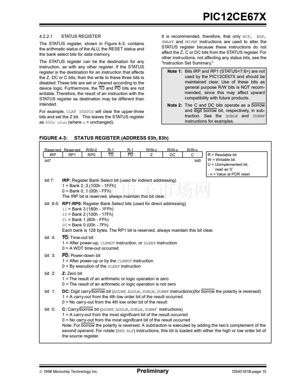
POWER CONTROL (PCON)/STATUS
REGISTER
The Power-up Timer provides a 铿亁ed 72 ms nominal
time-out on power-up only, from the POR. The Power-
up Timer operates on an internal RC oscillator. The
chip is kept in reset as long as the PWRT is active. The
PWRT鈥檚 time delay allows V
DD
to rise to an acceptable
level. A con铿乬uration bit is provided to enable/disable
the PWRT.
The power-up time delay will vary from chip to chip due
to V
DD
, temperature, and process variation. See DC
parameters for details.
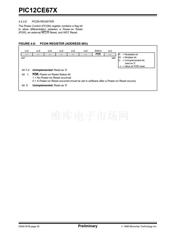
The power control/status register, PCON (address
8Eh) has one bit. See Figure 4-8 for register.
Bit1 is POR (Power-on Reset). It is cleared on a Power-
on Reset and is unaffected otherwise. The user set this
bit following a Power-on Reset. On subsequent resets
if POR is 鈥?鈥? it will indicate that a Power-on Reset must
have occurred.
TABLE 9-3:
TIME-OUT IN VARIOUS SITUATIONS
Power-up
PWRTE = 0
PWRTE = 1
72 ms + 1024T
OSC
1024T
OSC
72 ms
鈥?/div>
Wake-up from SLEEP
1024T
OSC
鈥?/div>
Oscillator Con铿乬uration
XT, HS, LP
INTRC, EXTRC
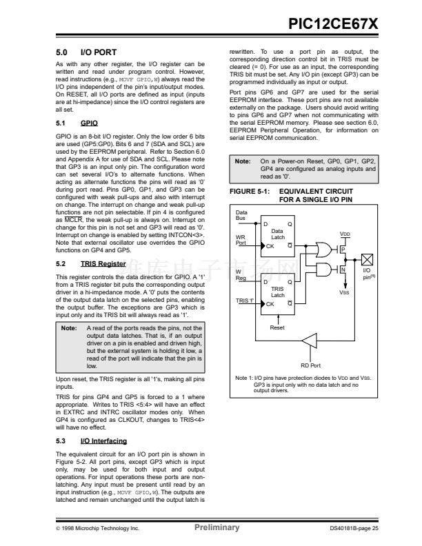
TABLE 9-4:
POR
0
0
0
1
1
1
1
TO
1
0
x
0
0
u
1
STATUS/PCON BITS AND THEIR SIGNIFICANCE
PD
1
x
0
u
0
u
0
Power-on Reset
Illegal, TO is set on POR
Illegal, PD is set on POR
WDT Reset
WDT Wake-up
MCLR Reset during normal operation
MCLR Reset during SLEEP or interrupt wake-up from SLEEP
DS40181B-page 50
Preliminary
漏
1998 Microchip Technology Inc.


 1
1
 2
2
 3
3
 4
4
 5
5
 6
6
 7
7
 8
8
 9
9
 10
10
 11
11
 12
12
 13
13
 14
14
 15
15
 16
16
 17
17
 18
18
 19
19
 20
20
 21
21
 22
22
 23
23
 24
24
 25
25
 26
26
 27
27
 28
28
 29
29
 30
30
 31
31
 32
32
 33
33
 34
34
 35
35
 36
36
 37
37
 38
38
 39
39
 40
40
 41
41
 42
42
 43
43
 44
44
 45
45
 46
46
 47
47
 48
48
 49
49
 50
50
 51
51
 52
52
 53
53
 54
54
 55
55
 56
56
 57
57
 58
58
 59
59
 60
60
 61
61
 62
62
 63
63
 64
64
 65
65
 66
66
 67
67
 68
68
 69
69
 70
70
 71
71
 72
72
 73
73
 74
74
 75
75
 76
76
 77
77
 78
78
 79
79
 80
80
 81
81
 82
82
 83
83
 84
84
 85
85
 86
86
 87
87
 88
88
 89
89
 90
90
 91
91
 92
92
 93
93
 94
94
 95
95
 96
96
 97
97
 98
98
 99
99
 100
100
 101
101
 102
102
 103
103
 104
104
 105
105
 106
106
 107
107
 108
108
 109
109
 110
110
 111
111
 112
112
 113
113
 114
114
 115
115
 116
116
