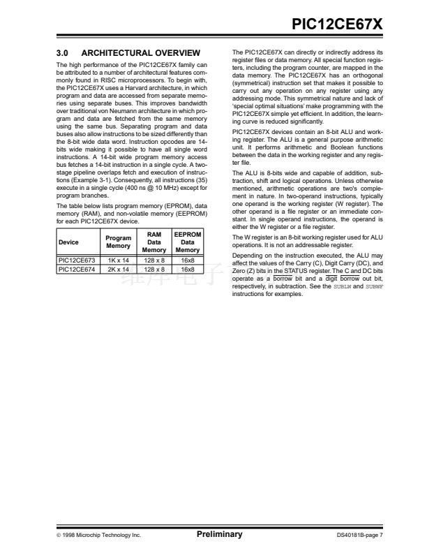
PIC12CE67X
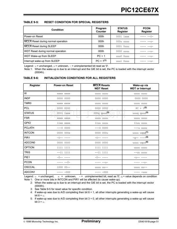
TABLE 9-5:
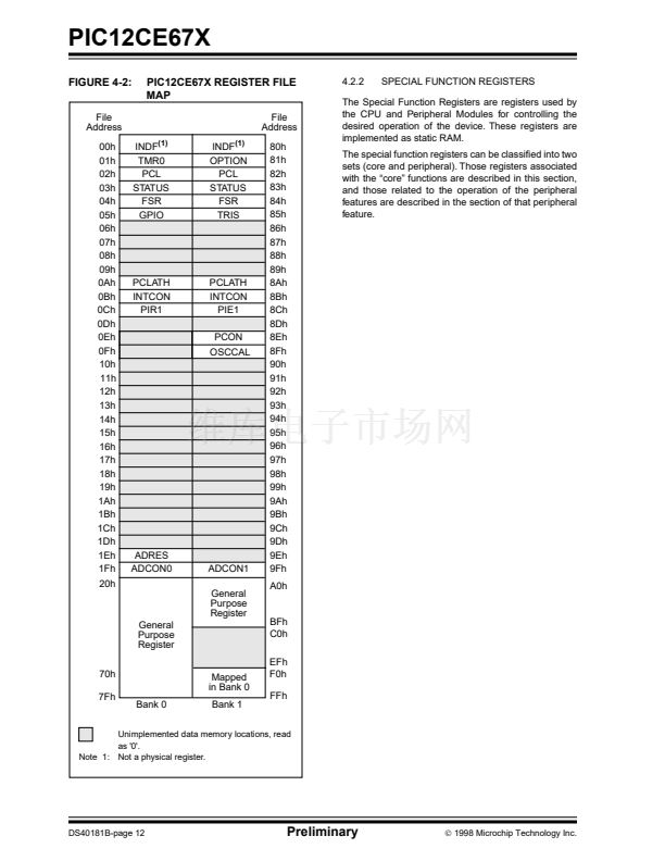
RESET CONDITION FOR SPECIAL REGISTERS
Condition
Power-on Reset
MCLR Reset during normal operation
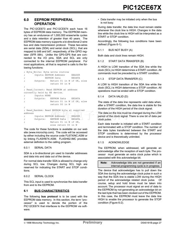
MCLR Reset during SLEEP
WDT Reset during normal operation
WDT Wake-up from SLEEP
Interrupt wake-up from SLEEP
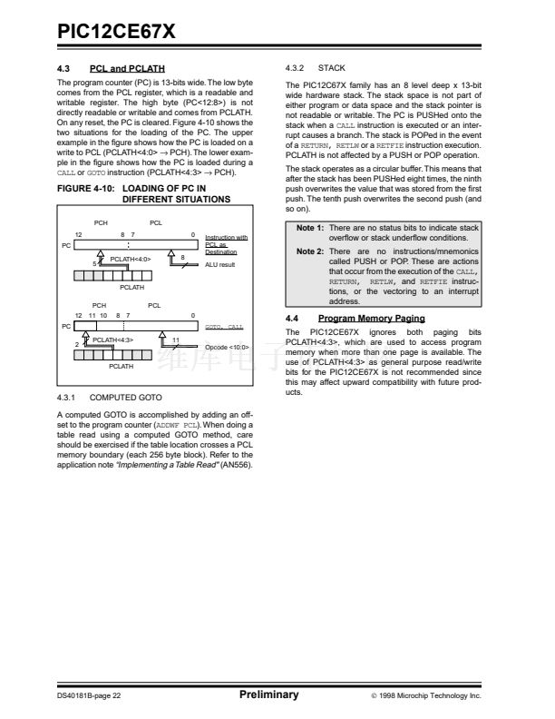
Program
Counter
000h
000h
000h
000h
PC + 1
PC + 1
(1)
STATUS
Register
0001 1xxx
000u uuuu
0001 0uuu
0000 uuuu
uuu0 0uuu
uuu1 0uuu
PCON
Register
---- --0-
---- --u-
---- --u-
---- --u-
---- --u-
---- --u-
Legend:
u
= unchanged,
x
= unknown,
-
= unimplemented bit read as '0'.
Note 1: When the wake-up is due to an interrupt and the GIE bit is set, the PC is loaded with the interrupt vector
(0004h).
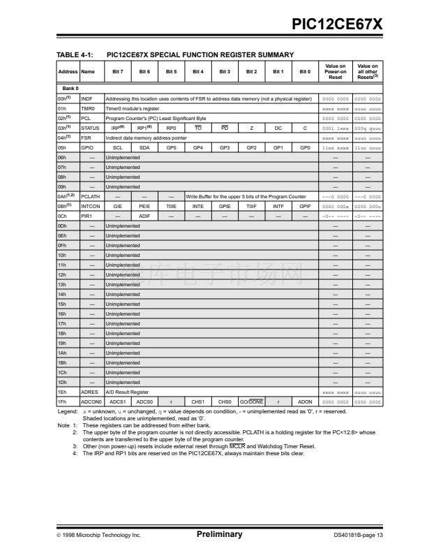
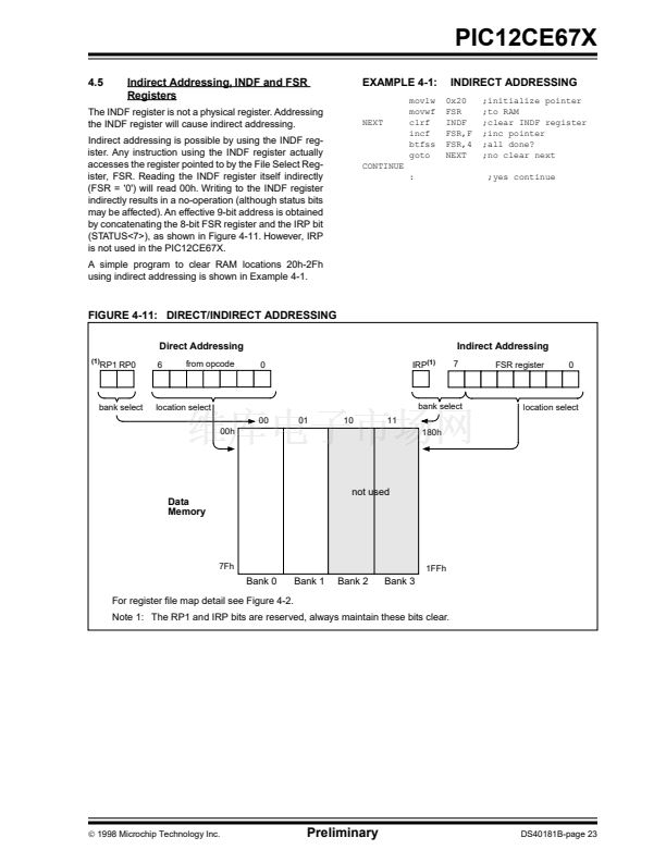
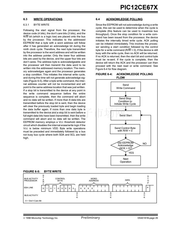
TABLE 9-6:
Register
W
INDF
TMR0
PCL
STATUS
FSR
GPIO
PCLATH
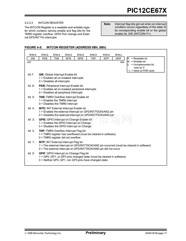
INTCON
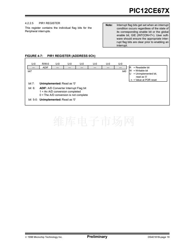
PIR1
ADCON0
OPTION
TRIS
PIE1
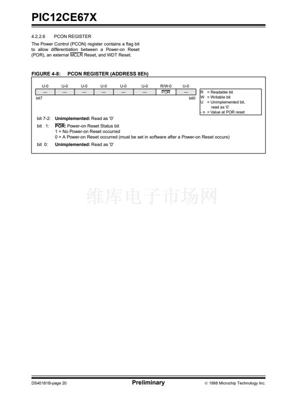
PCON
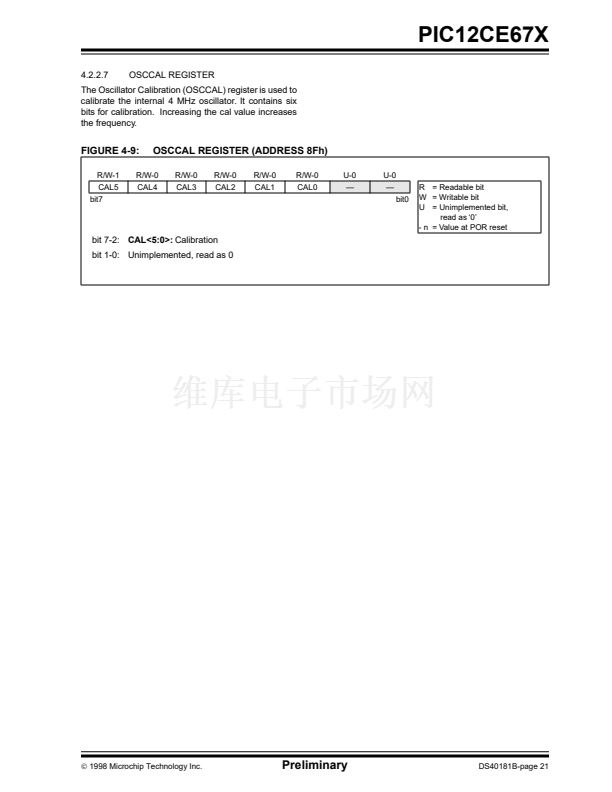
OSCCAL
ADCON1
INITIALIZATION CONDITIONS FOR ALL REGISTERS
Power-on Reset
xxxx xxxx
0000 0000
xxxx xxxx
0000 0000
0001 1xxx
xxxx xxxx
11xx xxxx
---0 0000
0000 000x
-0-- ----
0000 0000
1111 1111
--11 1111
-0-- ----
---- --0-
1000 00--
---- -000
MCLR Resets
WDT Reset
uuuu uuuu
0000 0000
uuuu uuuu
0000 0000
000q quuu
(3)
uuuu uuuu
11uu uuuu
---0 0000
0000 000u
-0-- ----
0000 0000
1111 1111
--11 1111
-0-- ----
---- --u-
uuuu uu--
---- -000
Wake-up via
WDT or Interrupt
uuuu uuuu
0000 0000
uuuu uuuu
PC + 1
(2)
uuuq quuu
(3)
uuuu uuuu
11uu uuuu
---u uuuu
uuuu uqqq
(1)
-q-- ----
(4)
uuuu uquu
(5)
uuuu uuuu
--uu uuuu
-u-- ----
---- --u-
uuuu uu--
---- -uuu
Legend:
u
= unchanged,
x
= unknown,
-
= unimplemented bit, read as '0',
q
= value depends on condition
Note 1: One or more bits in INTCON and PIR1 will be affected (to cause wake-up).
2: When the wake-up is due to an interrupt and the GIE bit is set, the PC is loaded with the interrupt vector
(0004h).
3: See Table 9-5 for reset value for speci铿乧 condition.
4: If wake-up was due to A/D completing then bit 6 = 1, all other interrupts generating a wake-up will cause
bit 6 =
u.
5: If wake-up was due to A/D completing then bit 3 = 0, all other interrupts generating a wake-up will cause
bit 3 =
u.
漏
1998 Microchip Technology Inc.
Preliminary
DS40181B-page 51


 1
1
 2
2
 3
3
 4
4
 5
5
 6
6
 7
7
 8
8
 9
9
 10
10
 11
11
 12
12
 13
13
 14
14
 15
15
 16
16
 17
17
 18
18
 19
19
 20
20
 21
21
 22
22
 23
23
 24
24
 25
25
 26
26
 27
27
 28
28
 29
29
 30
30
 31
31
 32
32
 33
33
 34
34
 35
35
 36
36
 37
37
 38
38
 39
39
 40
40
 41
41
 42
42
 43
43
 44
44
 45
45
 46
46
 47
47
 48
48
 49
49
 50
50
 51
51
 52
52
 53
53
 54
54
 55
55
 56
56
 57
57
 58
58
 59
59
 60
60
 61
61
 62
62
 63
63
 64
64
 65
65
 66
66
 67
67
 68
68
 69
69
 70
70
 71
71
 72
72
 73
73
 74
74
 75
75
 76
76
 77
77
 78
78
 79
79
 80
80
 81
81
 82
82
 83
83
 84
84
 85
85
 86
86
 87
87
 88
88
 89
89
 90
90
 91
91
 92
92
 93
93
 94
94
 95
95
 96
96
 97
97
 98
98
 99
99
 100
100
 101
101
 102
102
 103
103
 104
104
 105
105
 106
106
 107
107
 108
108
 109
109
 110
110
 111
111
 112
112
 113
113
 114
114
 115
115
 116
116
