Philips Semiconductors
BUK95/963R2-40B
TrenchMOS鈩?logic level FET
4. Thermal characteristics
Table 3:
R
th(j-mb)
R
th(j-a)
Thermal characteristics
Conditions
Figure 4
Min
-
Typ
-
Max Unit
0.5
K/W
thermal resistance from junction to
mounting base
thermal resistance from junction to
ambient
SOT78
SOT404
vertical in still air
mounted on a printed circuit board; minimum
footprint
-
-
60
50
-
-
K/W
K/W
Symbol Parameter
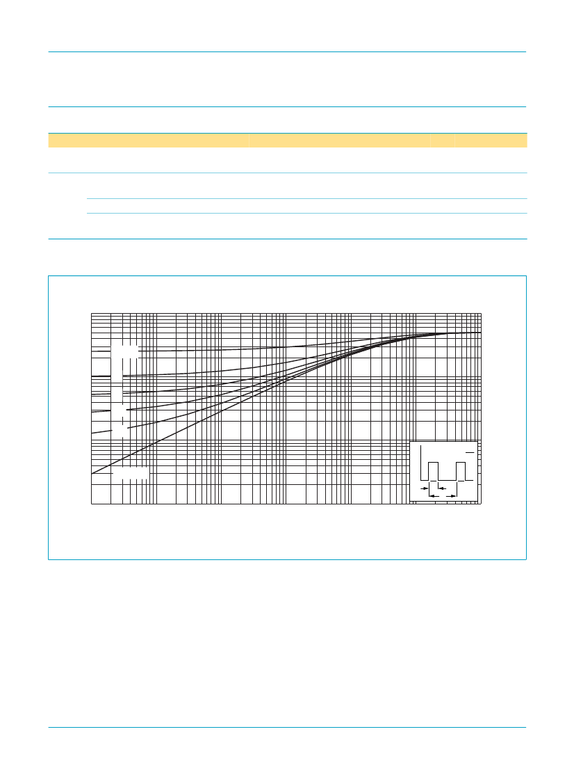
4.1 Transient thermal impedance
1
Zth(j-mb)
(K/W)
未
= 0.5
10-1
03nh37
0.2
0.1
0.05
0.02
10-2
P
未
=
tp
T
single shot
tp
t
T
10-3
10-6
10-5
10-4
10-3
10-2
10-1
tp (s)
1
Fig 4. Transient thermal impedance from junction to mounting base as a function of pulse duration.
9397 750 10844
漏 Koninklijke Philips Electronics N.V. 2003. All rights reserved.
Product data
Rev. 03 鈥?16 January 2003
4 of 15


 1
1
 2
2
 3
3
 4
4
 5
5
 6
6
 7
7
 8
8
 9
9
 10
10
 11
11
 12
12
 13
13
 14
14
 15
15
 16
16
