ADVANCE
INFORMATION
4.9.3
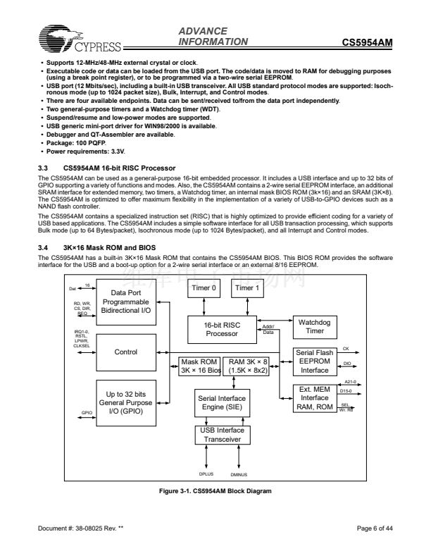
USB Endpoints Status (for Reading)
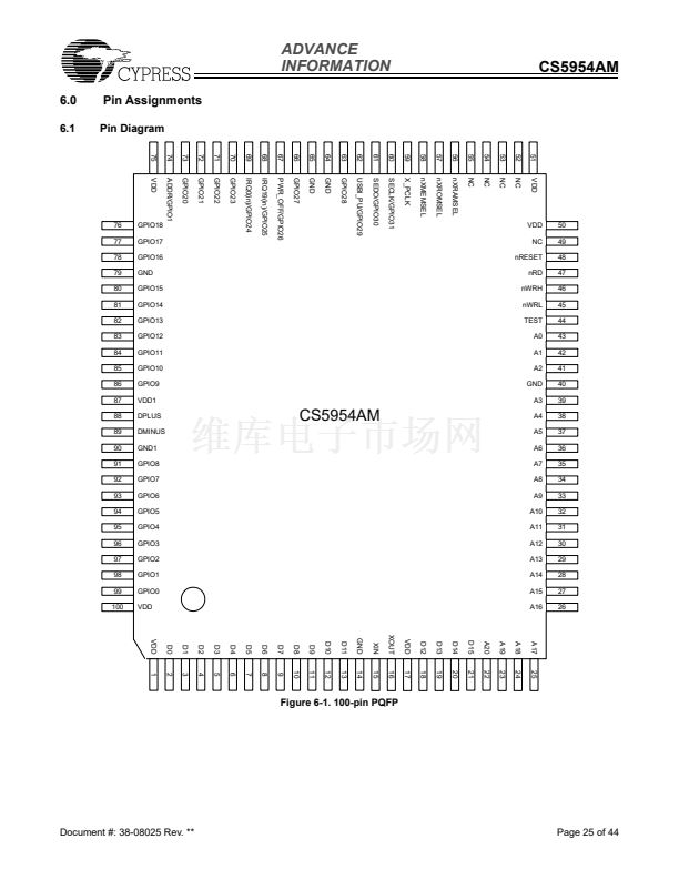
CS5954AM
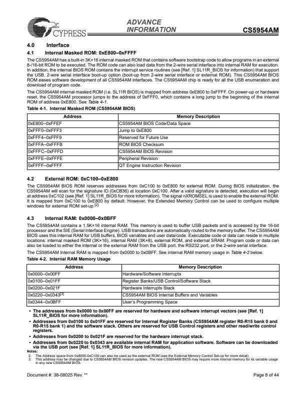
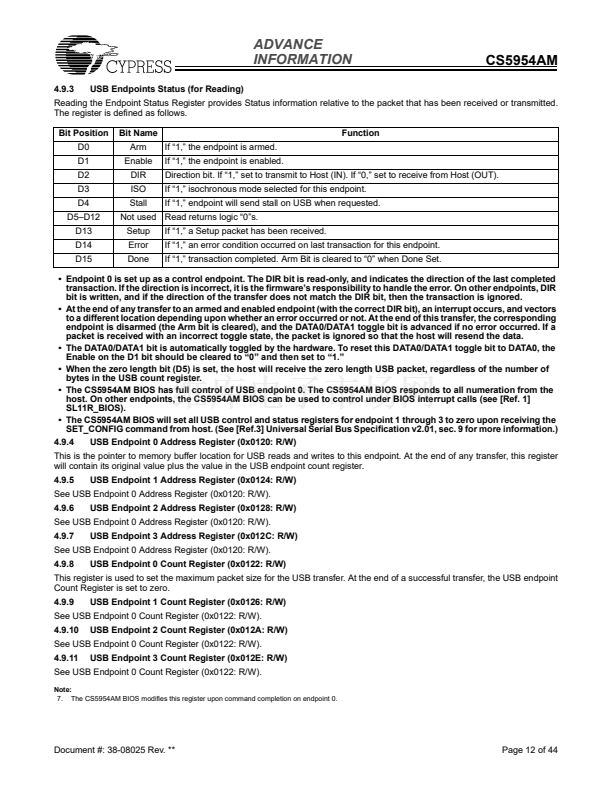
Reading the Endpoint Status Register provides Status information relative to the packet that has been received or transmitted.
The register is defined as follows.
Bit Position
D0
D1
D2
D3
D4
D5鈥揇12
D13
D14
D15
Bit Name
Arm
Enable
DIR
ISO
Stall
Setup
Error
Done
If 鈥?,鈥?the endpoint is armed.
If 鈥?,鈥?the endpoint is enabled.
Direction bit. If 鈥?,鈥?set to transmit to Host (IN). If 鈥?,鈥?set to receive from Host (OUT).
If 鈥?,鈥?isochronous mode selected for this endpoint.
If 鈥?,鈥?endpoint will send stall on USB when requested.
If 鈥?,鈥?a Setup packet has been received.
If 鈥?,鈥?an error condition occurred on last transaction for this endpoint.
If 鈥?,鈥?transaction completed. Arm Bit is cleared to 鈥?鈥?when Done Set.
Function
Not used Read returns logic 鈥?鈥漵.
鈥?Endpoint 0 is set up as a control endpoint. The DIR bit is read-only, and indicates the direction of the last completed
transaction. If the direction is incorrect, it is the firmware鈥檚 responsibility to handle the error. On other endpoints, DIR
bit is written, and if the direction of the transfer does not match the DIR bit, then the transaction is ignored.
鈥?At the end of any transfer to an armed and enabled endpoint (with the correct DIR bit), an interrupt occurs, and vectors
to a different location depending upon whether an error occurred or not. At the end of this transfer, the corresponding
endpoint is disarmed (the Arm bit is cleared), and the DATA0/DATA1 toggle bit is advanced if no error occurred. If a
packet is received with an incorrect toggle state, the packet is ignored so that the host will resend the data.
鈥?The DATA0/DATA1 bit is automatically toggled by the hardware. To reset this DATA0/DATA1 toggle bit to DATA0, the
Enable on the D1 bit should be cleared to 鈥?鈥?and then set to 鈥?.鈥?/div>
鈥?When the zero length bit (D5) is set, the host will receive the zero length USB packet, regardless of the number of
bytes in the USB count register.
鈥?The CS5954AM BIOS has full control of USB endpoint 0. The CS5954AM BIOS responds to all numeration from the
host. On other endpoints, the CS5954AM BIOS can be used to control under BIOS interrupt calls (see [Ref. 1]
SL11R_BIOS).
鈥?The CS5954AM BIOS will set all USB control and status registers for endpoint 1 through 3 to zero upon receiving the
SET_CONFIG command from host. (See [Ref.3] Universal Serial Bus Specification v2.01, sec. 9 for more information.)
4.9.4
USB Endpoint 0 Address Register (0x0120: R/W)
This is the pointer to memory buffer location for USB reads and writes to this endpoint. At the end of any transfer, this register
will contain its original value plus the value in the USB endpoint count register.
4.9.5
4.9.6
4.9.7
4.9.8
USB Endpoint 1 Address Register (0x0124: R/W)
USB Endpoint 2 Address Register (0x0128: R/W)
USB Endpoint 3 Address Register (0x012C: R/W)
USB Endpoint 0 Count Register (0x0122: R/W)
See USB Endpoint 0 Address Register (0x0120: R/W).
See USB Endpoint 0 Address Register (0x0120: R/W).
See USB Endpoint 0 Address Register (0x0120: R/W).
This register is used to set the maximum packet size for the USB transfer. At the end of a successful transfer, the USB endpoint
Count Register is set to zero.
4.9.9
4.9.10
4.9.11
USB Endpoint 1 Count Register (0x0126: R/W)
USB Endpoint 2 Count Register (0x012A: R/W)
USB Endpoint 3 Count Register (0x012E: R/W)
See USB Endpoint 0 Count Register (0x0122: R/W).
See USB Endpoint 0 Count Register (0x0122: R/W).
See USB Endpoint 0 Count Register (0x0122: R/W).
Note:
7. The CS5954AM BIOS modifies this register upon command completion on endpoint 0.
Document #: 38-08025 Rev. **
Page 12 of 44


 1
1
 2
2
 3
3
 4
4
 5
5
 6
6
 7
7
 8
8
 9
9
 10
10
 11
11
 12
12
 13
13
 14
14
 15
15
 16
16
 17
17
 18
18
 19
19
 20
20
 21
21
 22
22
 23
23
 24
24
 25
25
 26
26
 27
27
 28
28
 29
29
 30
30
 31
31
 32
32
 33
33
 34
34
 35
35
 36
36
 37
37
 38
38
 39
39
 40
40
 41
41
 42
42
 43
43
 44
44
