CS8416
15 APPENDIX B: CHANNEL STATUS
BUFFER MANAGEMENT
15.1
AES3 Channel Status (C) Bit
Management
transfers occur. This allows determination of the al-
lowable time periods to interact with the E buffer.
Also provided is a D to E inhibit bit. This may be
used whenever 鈥渓ong鈥?control port interactions are
occurring.
A flowchart for reading the E buffer is shown in
Figure 20.
Since a D to E interrupt just occurred af-
ter reading, there is a substantial time interval until
the next D to E transfer (approximately 192 frames
worth of time). This is usually plenty of time to ac-
cess the E data without having to inhibit the next
transfer.
The CS8416 contains sufficient RAM to store the
first 5 bytes of C data for both A and B channels
(5 x 2 x 8 = 80 bits). The user may read from this
buffer鈥檚 RAM through the control port.
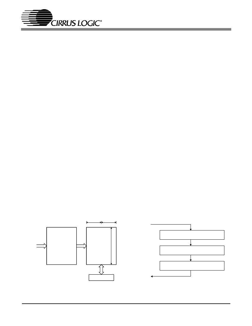
The buffering scheme involves 2 80-bit buffers,
named D and E, as shown in
Figure 19.
The MSB
of each byte represents the first bit in the serial C
data stream. For example, the MSB of byte 0
(which is at control port address 32) is the consum-
er/professional bit for channel status block A.
The first buffer (D) accepts incoming C data from
the AES receiver. The 2nd buffer (E) accepts entire
blocks of data from the D buffer. The E buffer is
also accessible from the control port, allowing
reading of the C data.
15.2.1 Serial Copy Management System
(SCMS)
In software mode, the CS8416 allows read access
to all the channel status bits. For consumer mode
SCMS compliance, the host microcontroller needs
to read and interpret the Category Code, Copy bit
and L bit appropriately.
In hardware mode, the SCMS protocol can be fol-
lowed by either using the COPY and ORIG output
pins, or by using the C bit serial output pin. These
options are documented in the hardware mode sec-
tion of this data sheet.
15.2
Accessing the E buffer
The user can monitor the incoming data by reading
the E buffer, which is mapped into the register
space of the CS8416, through the control port.
The user can configure the interrupt enable register
to cause interrupts to occur whenever D to E buffer
A
8-bits
From
AES3
Receiver
B
8-bits
D to E interrupt occurs
Optionally set D to E inhibit
Read E data
If set, clear D to E inhibit
D
Received
Data
Buffer
E
24
words
Control Port
Return
Figure 20. Flowchart for Reading the E Buffer
Figure 19. Channel Status Data Buffer Structure
DS578PP2
47


 1
1
 2
2
 3
3
 4
4
 5
5
 6
6
 7
7
 8
8
 9
9
 10
10
 11
11
 12
12
 13
13
 14
14
 15
15
 16
16
 17
17
 18
18
 19
19
 20
20
 21
21
 22
22
 23
23
 24
24
 25
25
 26
26
 27
27
 28
28
 29
29
 30
30
 31
31
 32
32
 33
33
 34
34
 35
35
 36
36
 37
37
 38
38
 39
39
 40
40
 41
41
 42
42
 43
43
 44
44
 45
45
 46
46
 47
47
 48
48
