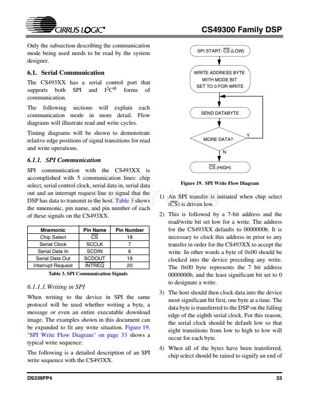
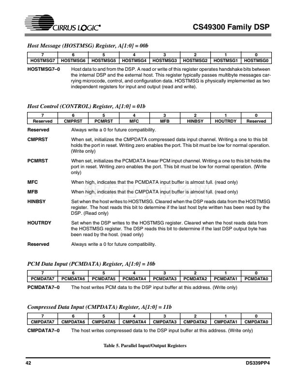
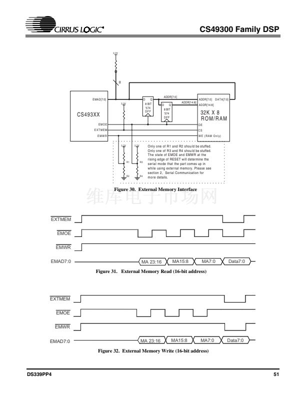
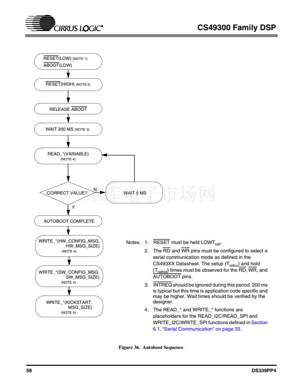
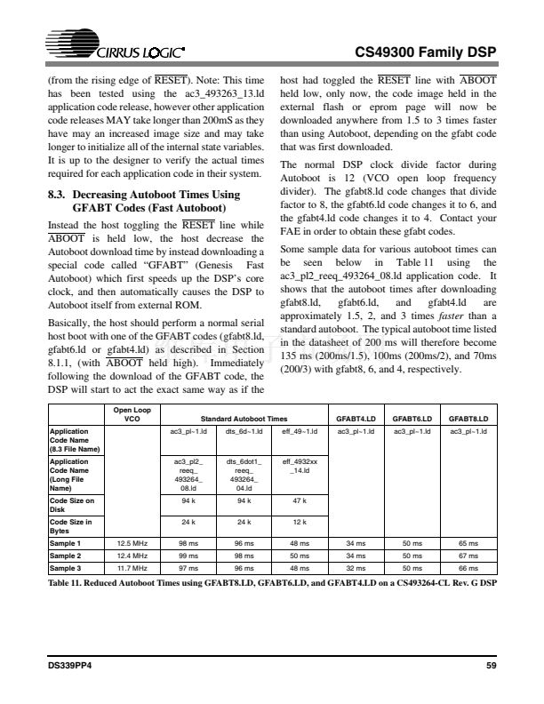
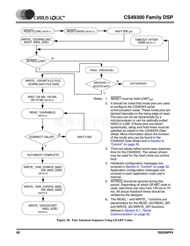
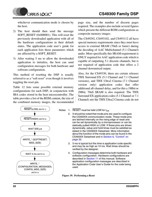
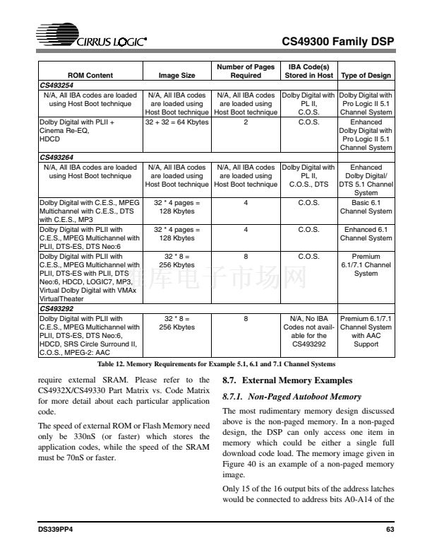
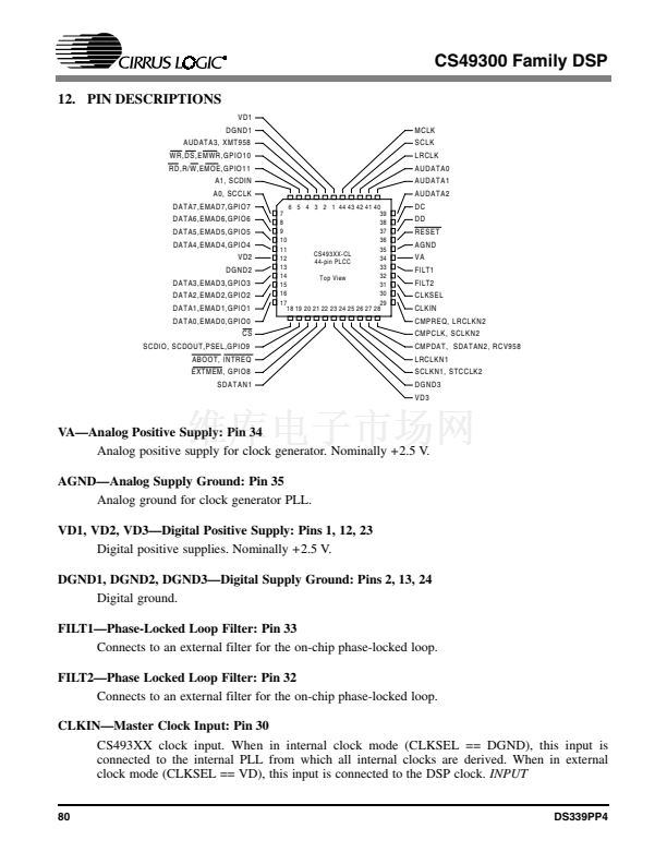
CS49300 Family DSP
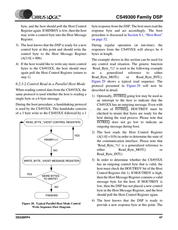
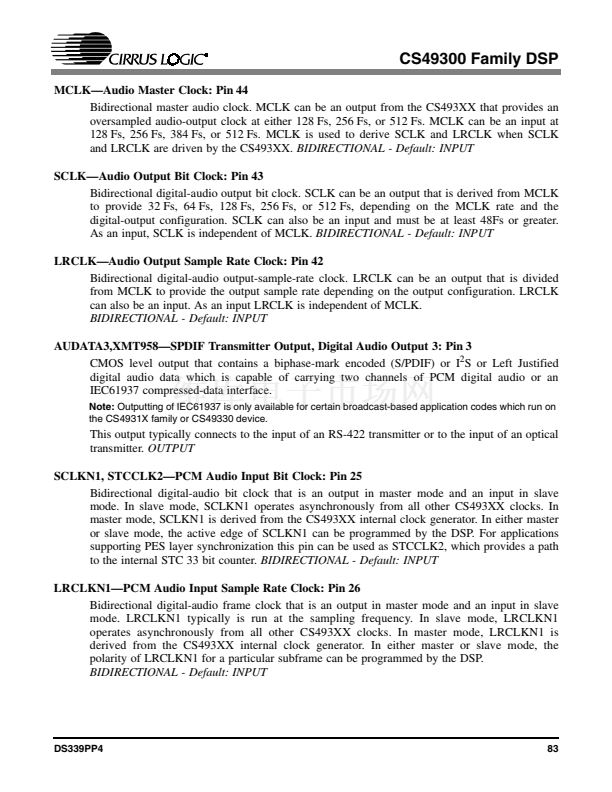
byte, and the host should poll the Host Control
Register again. If HINBSY is low, then the host
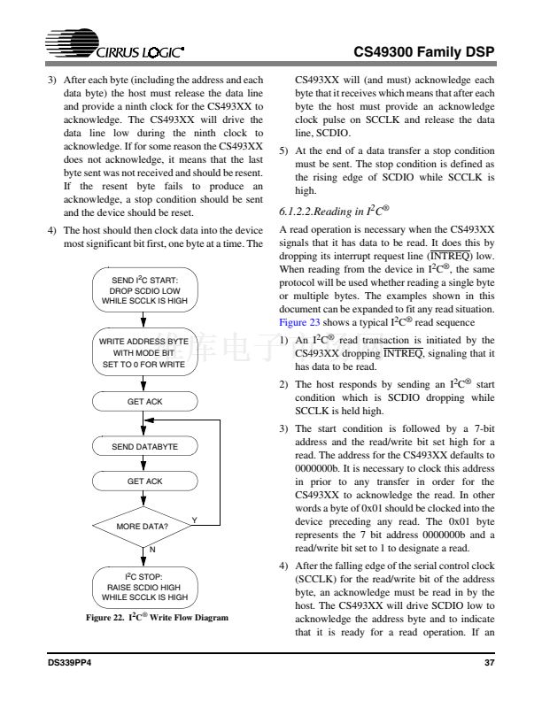
may write a control byte into the Host Message
Register.
3) The host knows that the DSP is ready for a new
control byte at this point and should write the
control byte to the Host Message Register
(A[1:0] = 00b).
4) If the host would like to write any more control
bytes to the CS493XX, the host should once
again poll the Host Control Register (return to
step 1).
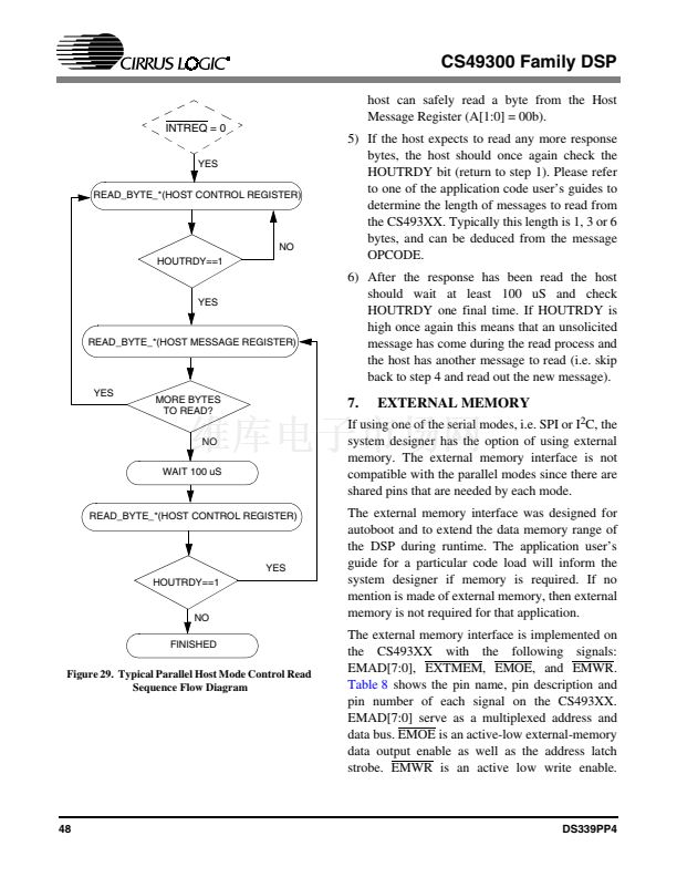
byte response from the DSP. The host must read the
response byte and act accordingly. The boot
procedure is discussed in
Section 8.1, 鈥淗ost Boot鈥?/span>
on page 52.
During regular operation (at run-time), the
responses from the CS493XX will always be 6
bytes in length.
The example shown in this section can be used for
any control read situation. The generic function
鈥楻ead_Byte_*()鈥?is used in the following example
as
a
generalized
reference
to
either
Read_Byte_MOT()
or
Read_Byte_INT().
Figure 29
shows a typical read sequence. The
protocol presented in
Figure 29
will now be
described in detail.
1) Optionally, INTREQ going low may be used as
an interrupt to the host to indicate that the
CS493XX has an outgoing message. Even with
the use of INTREQ, HOUTRDY must be
checked to insure that bytes are ready for the
host during the read process. Please note that
INTREQ does not go low to indicate an
outgoing message during boot.
2) The host reads the Host Control Register
(A[1:0] = 01b) in order to determine the state of
the communication interface. Please note that
鈥楻ead_Byte_*()鈥?is a generalized reference to
either
Read_Byte_MOT()
or
Read_Byte_INT().
3) In order to determine whether the CS493XX
has an outgoing control byte that is valid, the
host must check the HOUTRDY bit of the Host
Control Register (bit 1). If HOUTRDY is high,
then the Host Message Register contains a valid
message byte for the host. If HOUTRDY is
low, then the DSP has not placed a new control
byte in the Host Message Register, and the host
should poll the Host Control Register again.
4) The host knows that the DSP is ready to
provide a new response byte at this point. The
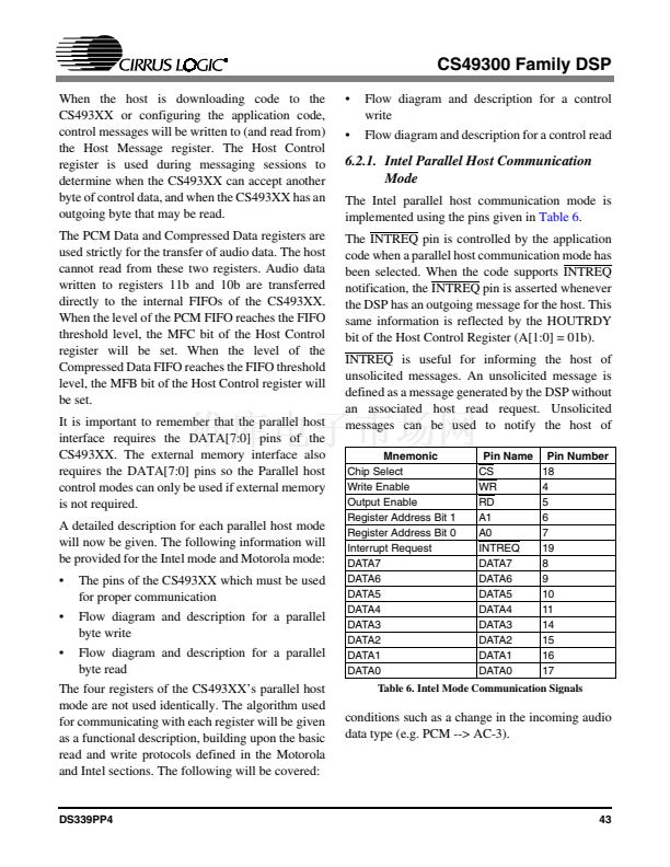
6.2.3.2.Control Read in a Parallel Host Mode
When reading control data from the CS493XX, the
same protocol is used whether the host is reading a
single byte or a 6 byte message.
During the boot procedure, a handshaking protocol
is used by the CS493XX. This handshake consists
of a 3 byte write to the CS493XX followed by a 1
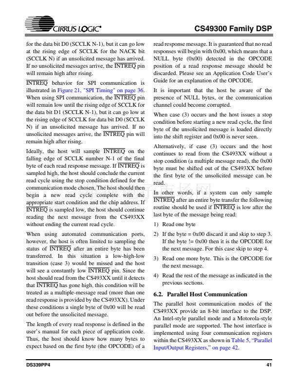
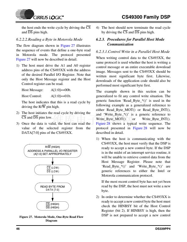
READ_BYTE_*(HOST CONTROL REGISTER)
YES
HINSBY==1
NO
WRITE_BYTE_*(HOST MESSAGE REGISTER)
YES
MORE BYTES
TO WRITE?
NO
FINISHED
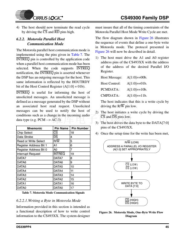
Figure 28. Typical Parallel Host Mode Control
Write Sequence Flow Diagram
DS339PP4
47


 1
1
 2
2
 3
3
 4
4
 5
5
 6
6
 7
7
 8
8
 9
9
 10
10
 11
11
 12
12
 13
13
 14
14
 15
15
 16
16
 17
17
 18
18
 19
19
 20
20
 21
21
 22
22
 23
23
 24
24
 25
25
 26
26
 27
27
 28
28
 29
29
 30
30
 31
31
 32
32
 33
33
 34
34
 35
35
 36
36
 37
37
 38
38
 39
39
 40
40
 41
41
 42
42
 43
43
 44
44
 45
45
 46
46
 47
47
 48
48
 49
49
 50
50
 51
51
 52
52
 53
53
 54
54
 55
55
 56
56
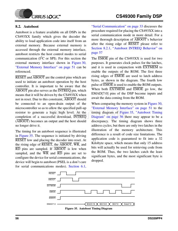
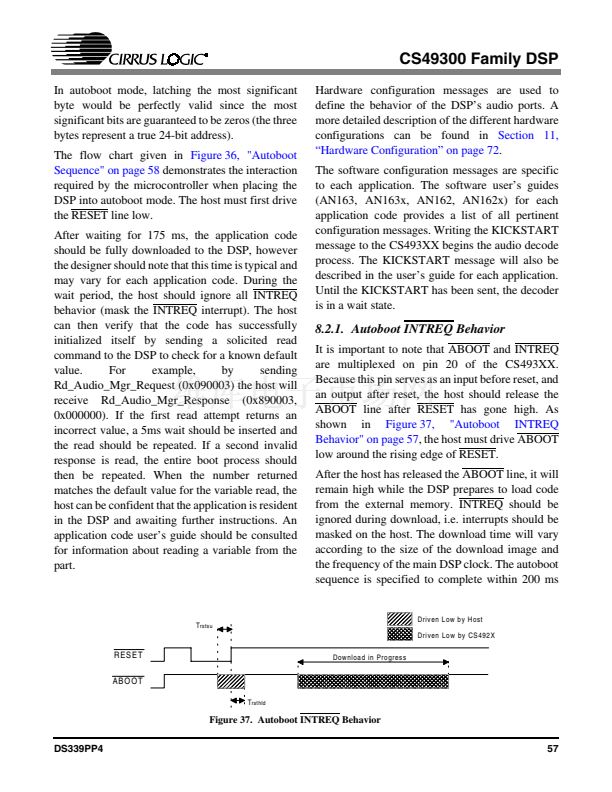 57
57
 58
58
 59
59
 60
60
 61
61
 62
62
 63
63
 64
64
 65
65
 66
66
 67
67
 68
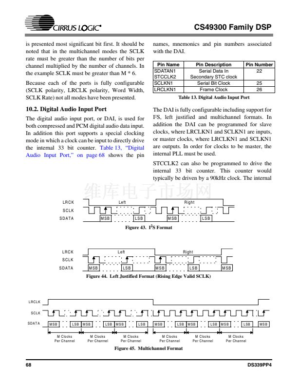
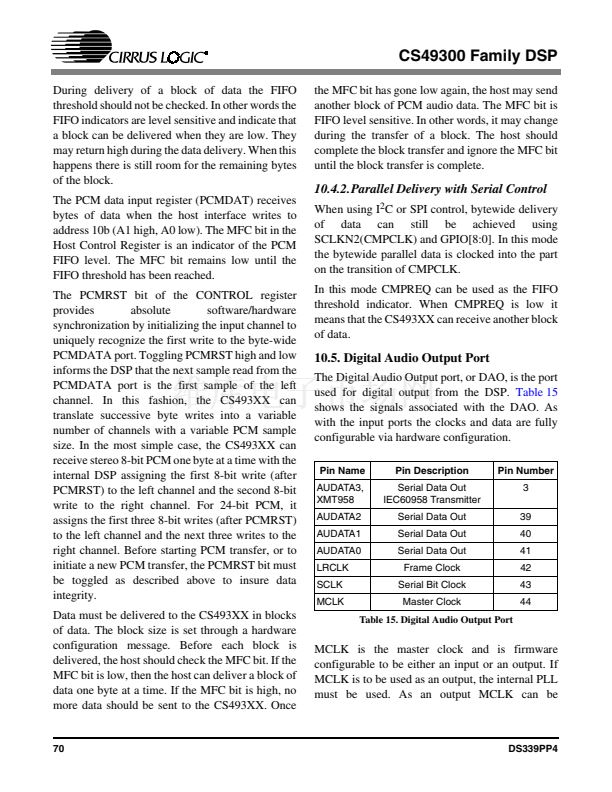
68
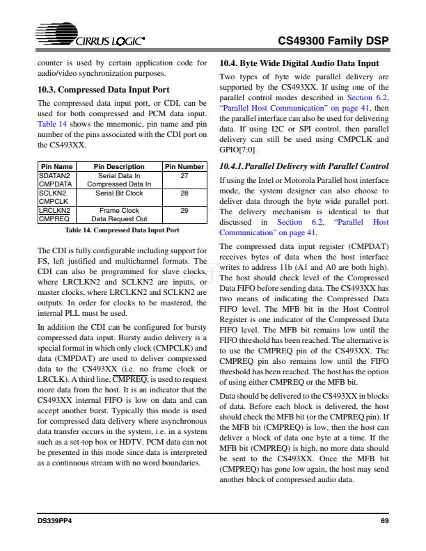 69
69
 70
70
 71
71
 72
72
 73
73
 74
74
 75
75
 76
76
 77
77
 78
78
 79
79
 80
80
 81
81
 82
82
 83
83
 84
84
 85
85
 86
86
