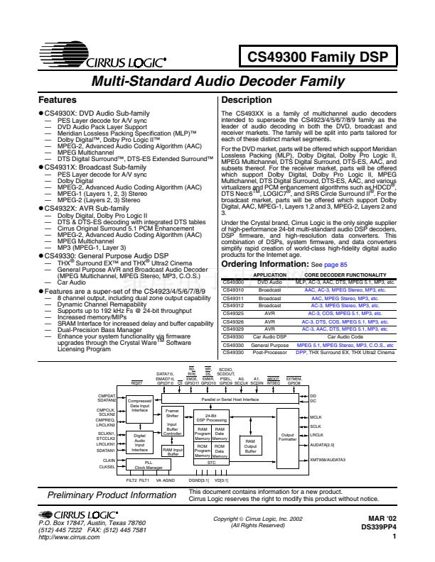
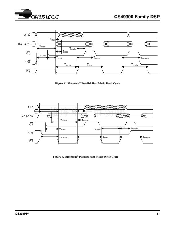
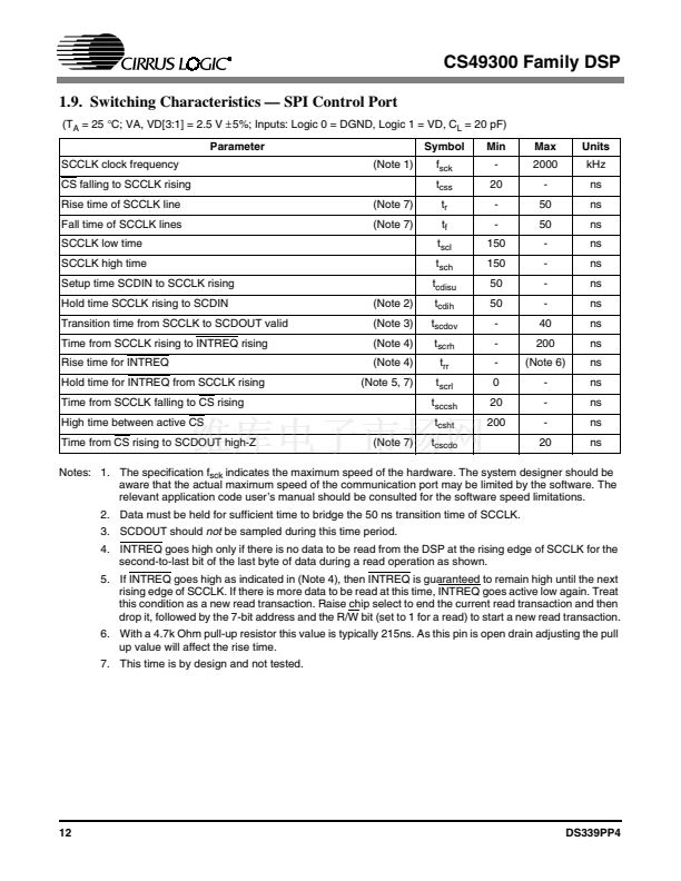
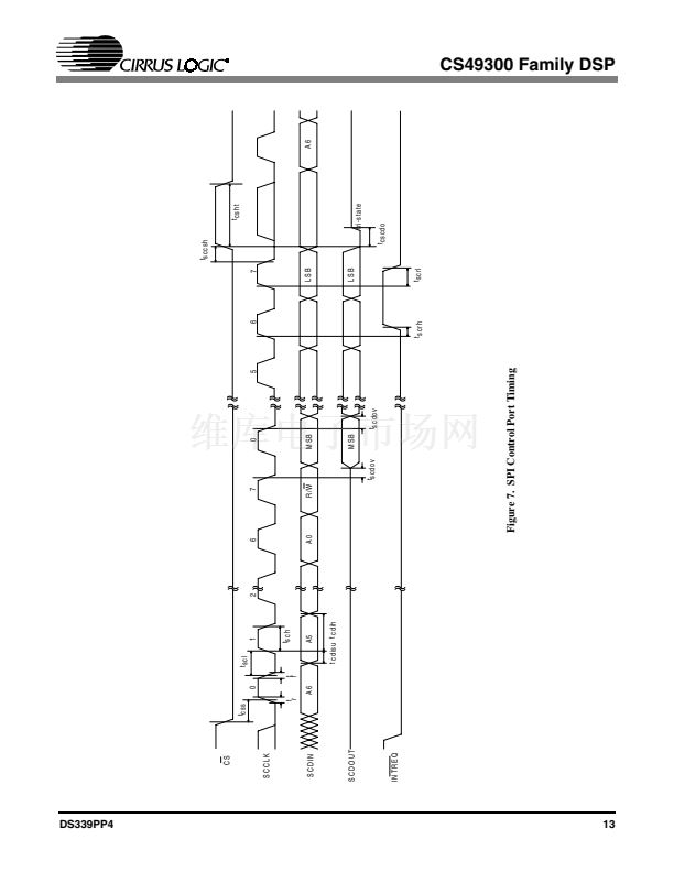
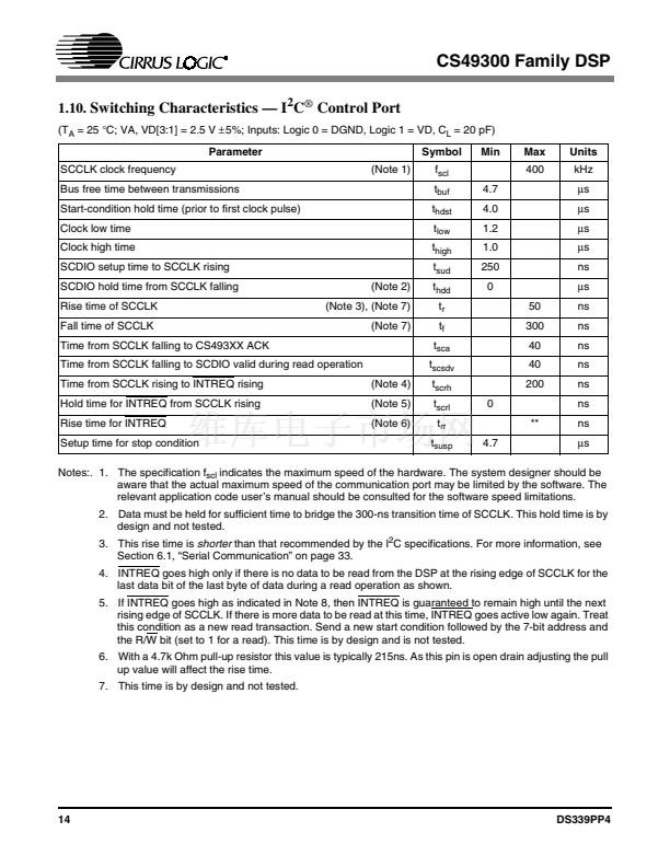
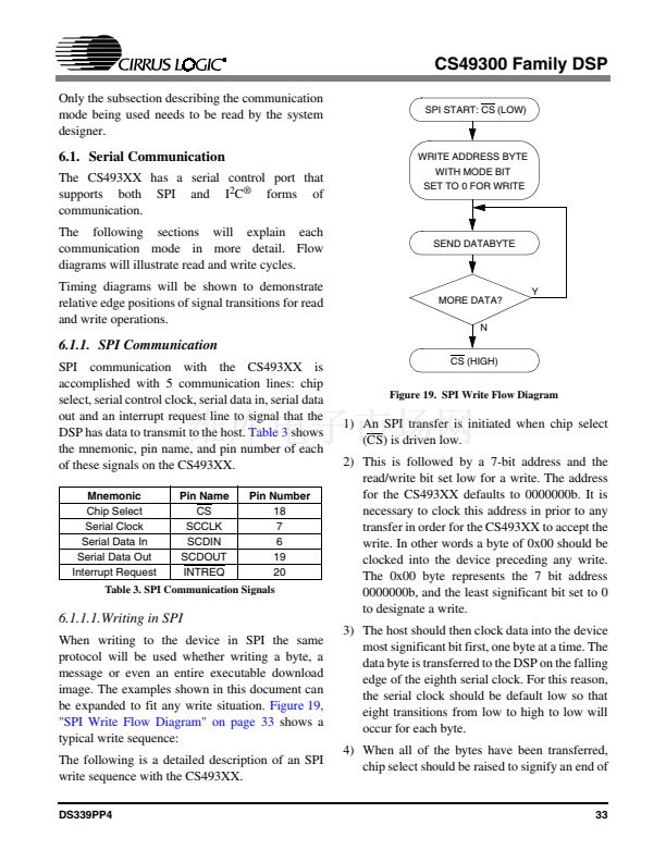
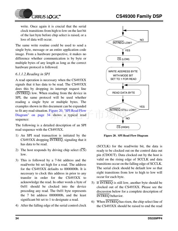
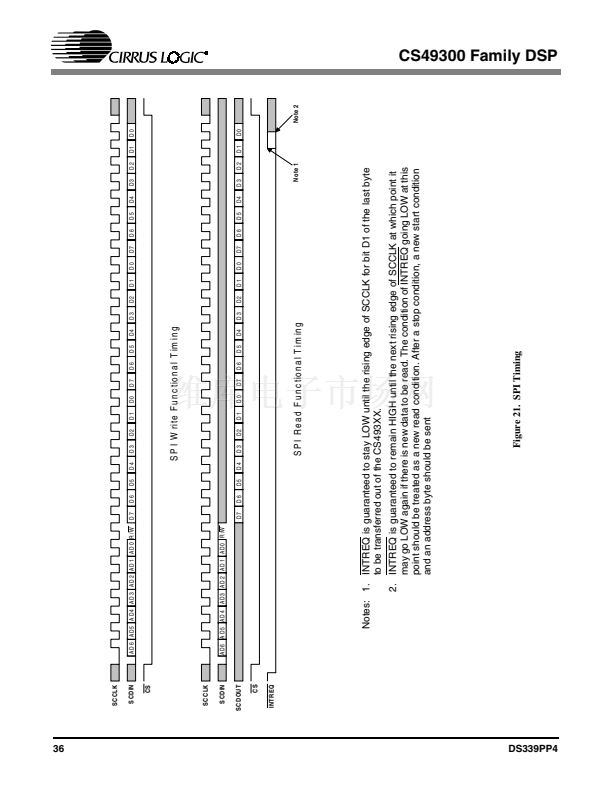
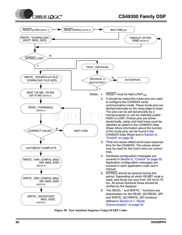
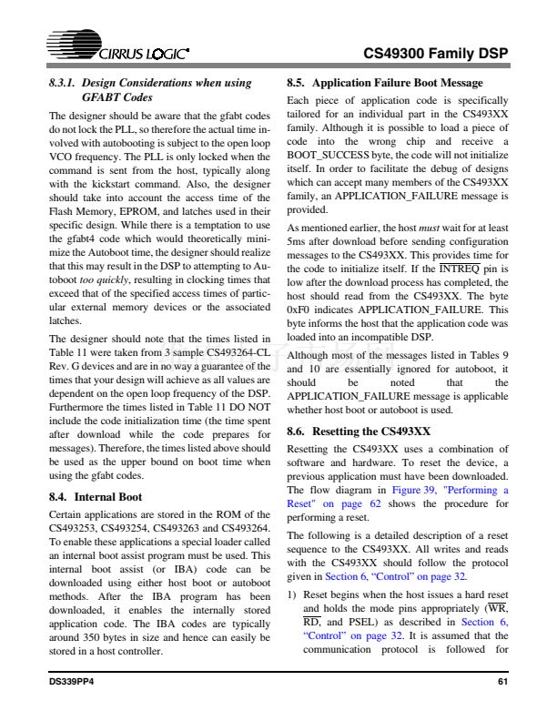
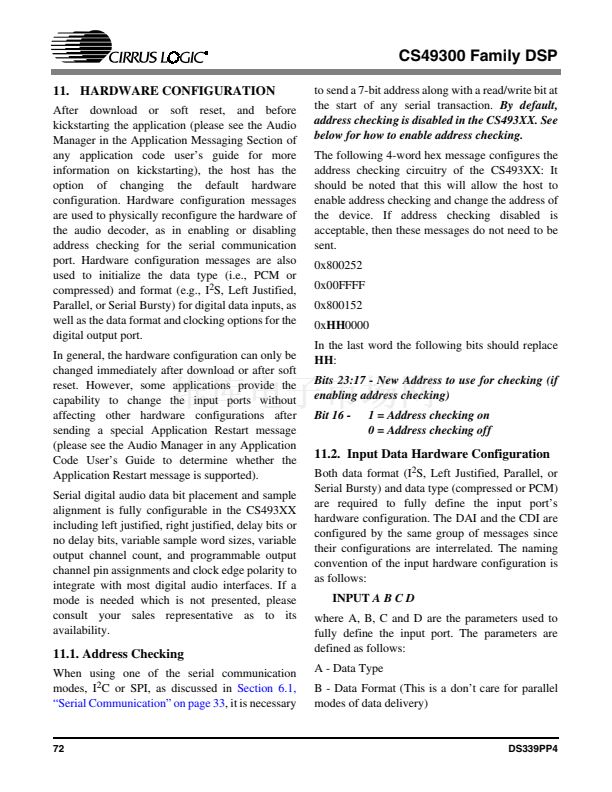
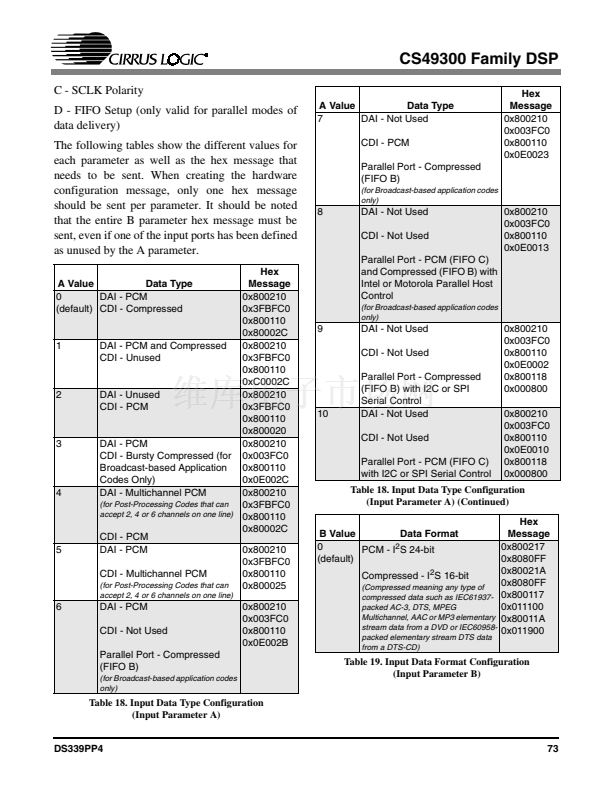
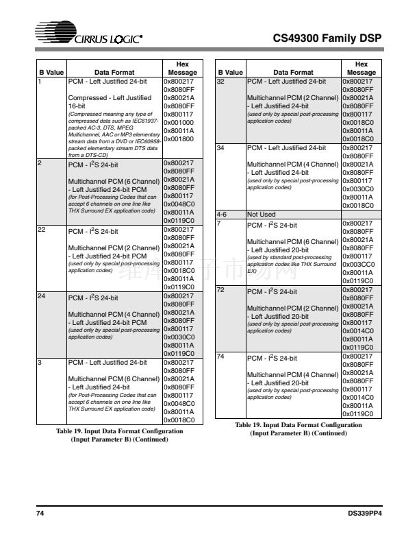
CS49300 Family DSP
CLKSEL鈥擠SP Clock Select: Pin 31
This pin selects the clock mode of the CS493XX. When CLKSEL is low, CLKIN is connected
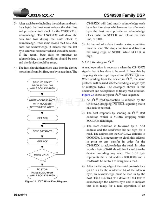
to the internal PLL from which all internal clocks are derived. When CLKSEL is high CLKIN
is connected to the DSP clock.
INPUT
DATA7, EMAD7, GPIO7鈥擯in 8
DATA6, EMAD6, GPIO6鈥擯in 9
DATA5, EMAD5, GPIO5鈥擯in 10
DATA4, EMAD4, GPIO4鈥擯in 11
DATA3, EMAD3, GPIO3鈥擯in 14
DATA2, EMAD2, GPIO2鈥擯in 15
DATA1, EMAD1, GPIO1鈥擯in 16
DATA0, EMAD0, GPIO0鈥擯in 17
In parallel host mode, these pins provide a bidirectional data bus. If a serial host mode is
selected, these pins can provide a multiplexed address and data bus for connecting an 8-bit
external memory. Otherwise, in serial host mode, these pins can act as general-purpose input or
output pins that can be individually configured and controlled by the DSP.
BIDIRECTIONAL - Default: INPUT
A0, SCCLK鈥擧ost Parallel Address Bit Zero or Serial Control Port Clock: Pin 7
In parallel host mode, this pin serves as one of two address input pins used to select one of four
parallel registers. In serial host mode, this pin serves as the serial control clock signal,
specifically as the SPI clock input or the I
2
C clock input.
INPUT
A1, SCDIN鈥擧ost Address Bit One or SPI Serial Control Data Input: Pin 6
In parallel host mode, this pin serves as one of two address input pins used to select one of four
parallel registers. In SPI serial host mode, this pin serves as the data input.
INPUT
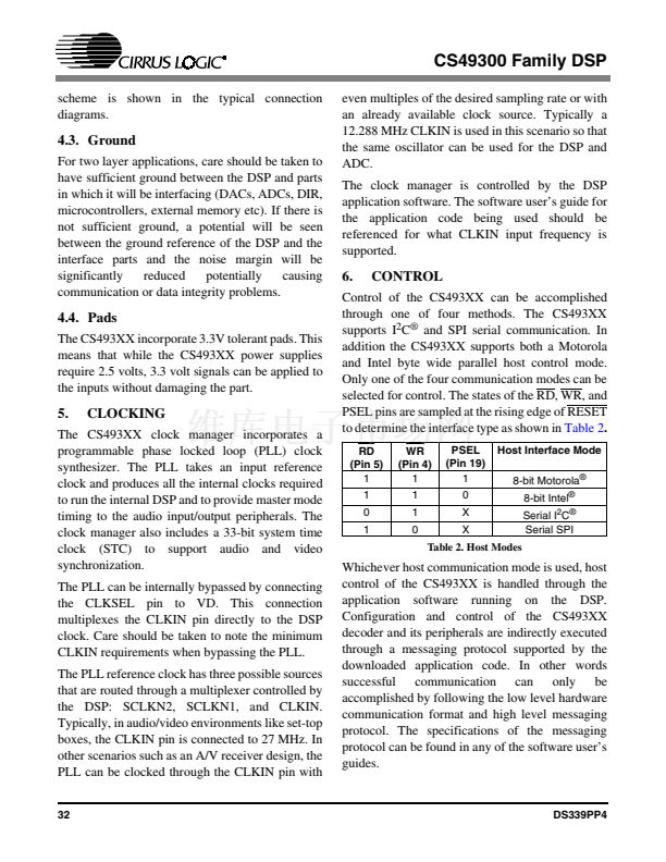
RD, R/W, EMOE, GPIO11鈥擧ost Parallel Output Enable or Host Parallel R/W or External
Memory Output Enable or General Purpose Input & Output Number 11: Pin 5
In Intel parallel host mode, this pin serves as the active-low data bus enable input. In Motorola
parallel host mode, this pin serves as the read-high/write-low control input signal. In serial host
mode, this pin can serve as the external memory active-low data-enable output signal. Also in
serial host mode, this pin can serve as a general purpose input or output bit.
BIDIRECTIONAL - Default: INPUT
WR, DS, EMWR, GPIO10鈥擧ost Write Strobe or Host Data Strobe or External Memory Write
Enable or General Purpose Input & Output Number 10: Pin 4
In Intel parallel host mode, this pin serves as the active-low data-write-input strobe. In
Motorola parallel host mode, this pin serves as the active-low data-strobe-input signal. In serial
host mode, this pin can serve as the external-memory active-low write-enable output signal.
Also in serial host mode, this pin can serve as a general purpose input or output bit.
BIDIRECTIONAL - Default: INPUT
DS339PP4
81


 1
1
 2
2
 3
3
 4
4
 5
5
 6
6
 7
7
 8
8
 9
9
 10
10
 11
11
 12
12
 13
13
 14
14
 15
15
 16
16
 17
17
 18
18
 19
19
 20
20
 21
21
 22
22
 23
23
 24
24
 25
25
 26
26
 27
27
 28
28
 29
29
 30
30
 31
31
 32
32
 33
33
 34
34
 35
35
 36
36
 37
37
 38
38
 39
39
 40
40
 41
41
 42
42
 43
43
 44
44
 45
45
 46
46
 47
47
 48
48
 49
49
 50
50
 51
51
 52
52
 53
53
 54
54
 55
55
 56
56
 57
57
 58
58
 59
59
 60
60
 61
61
 62
62
 63
63
 64
64
 65
65
 66
66
 67
67
 68
68
 69
69
 70
70
 71
71
 72
72
 73
73
 74
74
 75
75
 76
76
 77
77
 78
78
 79
79
 80
80
 81
81
 82
82
 83
83
 84
84
 85
85
 86
86
