DM74LS534
Functional Description
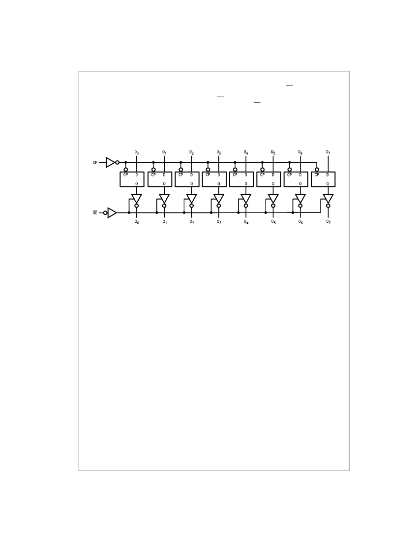
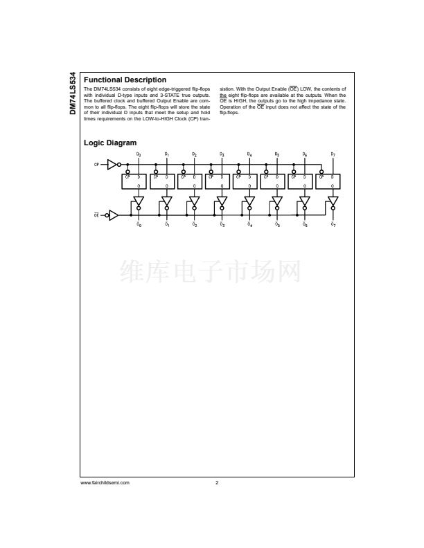
The DM74LS534 consists of eight edge-triggered flip-flops
with individual D-type inputs and 3-STATE true outputs.
The buffered clock and buffered Output Enable are com-
mon to all flip-flops. The eight flip-flops will store the state
of their individual D inputs that meet the setup and hold
times requirements on the LOW-to-HIGH Clock (CP) tran-
sistion. With the Output Enable (OE) LOW, the contents of
the eight flip-flops are available at the outputs. When the
OE is HIGH, the outputs go to the high impedance state.
Operation of the OE input does not affect the state of the
flip-flops.
Logic Diagram
www.fairchildsemi.com
2


 1
1
 2
2
 3
3
 4
4
 5
5
