Application hints
LIS3L02AL
4
Application hints
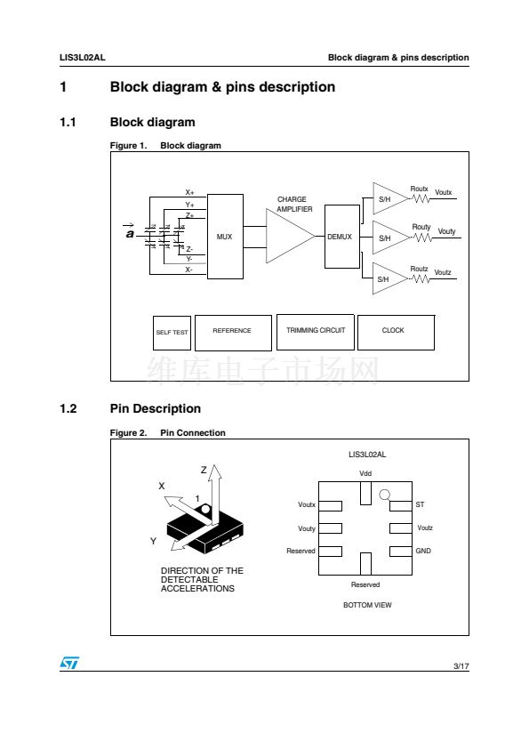
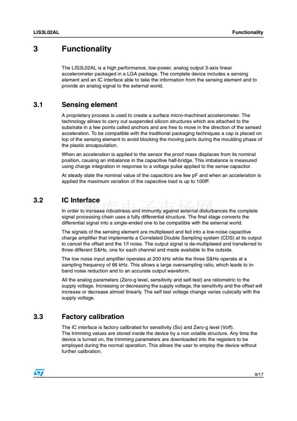
Figure 3.
LIS3L02AL electrical connection
Vdd
10碌F
GND
100nF
GND
ST
Z
Optional
Vout X
X
1
LIS3L02AL
(top view)
GND
Cload x
Optional
Vout Y
Cload y
Y
DIRECTION OF THE
DETECTABLE
ACCELERATIONS
Optional
Vout Z
Cload z
Digital signals
Power supply decoupling capacitors (100nF ceramic or polyester + 10碌F Aluminum) should
be placed as near as possible to the device (common design practice).
The LIS3L02AL allows to band limit Voutx, Vouty and Voutz through the use of external
capacitors. The re-commended frequency range spans from DC up to 1.5 KHz. In particular,
capacitors must be added at output pins to implement low-pass filtering for antialiasing and
noise reduction. The equation for the cut-off frequency (f
t
) of the external filters is:
1
f t = -------------------------------------------------------------------
-
2蟺
鈰?/div>
R out
鈰?/div>
C load
(
x, y, z
)
Taking in account that the internal filtering resistor (R
out
) has a nominal value equal to
110k鈩? the equation for the external filter cut-off frequency may be simplified as follows:
1.45碌F
f t = ------------------------------------
[
Hz
]
-
C load
(
x, y, z
)
The tolerance of the internal resistor can vary typically of 卤20% within its nominal value of
110k鈩? thus the cut-off frequency will vary accordingly. A minimum capacitance of 1nF for
C
load
(x, y, z) is required in any case.
Table 5.
.
Filter capacitor selection, C
load
(x,y,z)
Cut-off frequency
1 Hz
10 Hz
20 Hz
50 Hz
100 Hz
200 Hz
500 Hz
Capacitor value
1500 nF
150 nF
68 nF
30 nF
15 nF
6.8 nF
3 nF
10/17


 1
1
 2
2
 3
3
 4
4
 5
5
 6
6
 7
7
 8
8
 9
9
 10
10
 11
11
 12
12
 13
13
 14
14
 15
15
 16
16
 17
17
