铮?/div>
3.3V
OR 5V
D1
C
C
R
C
C
C
R
C
I
TH
/RUN
I
TH
/RUN
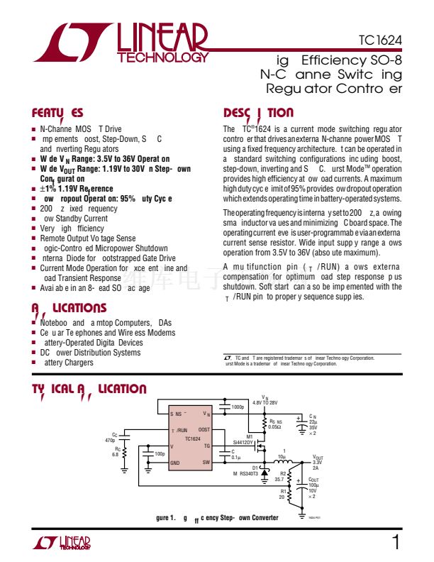
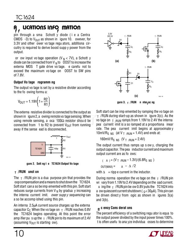
The external resistive divider is connected to the output as
shown in Figure 2, allowing remote voltage sensing. When
using remote sensing, a local 100鈩?resistor should be
connected from L1 to R2 to prevent V
OUT
from running
away if the sense lead is disconnected.
L1
R2
V
FB
LTC1624
GND
1624 F02
V
OUT
100pF
R1
Figure 2. Setting the LTC1624 Output Voltage
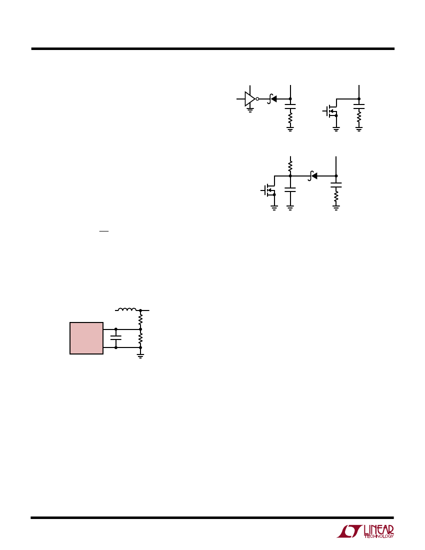
I
TH
/RUN Function
The I
TH
/RUN pin is a dual purpose pin that provides the
loop compensation and a means to shut down the LTC1624.
Soft start can also be implemented with this pin. Soft start
reduces surge currents from V
IN
by gradually increasing
the internal current limit.
Power supply sequencing
can
also be accomplished using this pin.
An internal 2.5碌A current source charges up the external
capacitor C
C.
When the voltage on I
TH
/RUN reaches 0.8V
the LTC1624 begins operating. At this point the error
amplifier pulls up the I
TH
/RUN pin to its maximum of 2.4V
(assuming V
OUT
is starting low).
10
U
W
U
U
(a)
I
TH
/RUN
R1
D1
(b)
C1
C
C
R
C
(c)
1624 F03
Figure 3. I
TH
/ RUN Pin Interfacing
Soft start can be implemented by ramping the voltage on
I
TH
/RUN during start-up as shown in Figure 3(c). As the
voltage on I
TH/RUN
ramps from 1.19V to 2.4V the internal
peak current limit is also ramped at a proportional linear
rate. The peak current limit begins at approximately
10mV/R
SENSE
(at V
ITH/RUN
= 1.4V) and ends at:
160mV/R
SENSE
(V
ITH/RUN
= 2.4V)
The output current thus ramps up slowly, charging the
output capacitor. The peak inductor current and maximum
output current are as follows:
I
L(PEAK)
= (V
ITH/RUN
鈥?1.3V)/(6.8R
SENSE
)
I
OUT(MAX)
= I
LPEAK
鈥?/div>
鈭咺
L
/ 2
with
鈭咺
L
= ripple current in the inductor.
During normal operation the voltage on the I
TH
/RUN pin
will vary from 1.19V to 2.4V depending on the load current.
Pulling the I
TH
/RUN pin below 0.8V puts the LTC1624 into
a low quiescent current shutdown (I
Q
< 30碌A). This pin can
be driven directly from logic as shown in Figures 3(a)
and 3(b).
Efficiency Considerations
The percent efficiency of a switching regulator is equal to
the output power divided by the input power times 100%.
It is often useful to analyze individual losses to determine


 1
1
 2
2
 3
3
 4
4
 5
5
 6
6
 7
7
 8
8
 9
9
 10
10
 11
11
 12
12
 13
13
 14
14
 15
15
 16
16
 17
17
 18
18
 19
19
 20
20
 21
21
 22
22
 23
23
 24
24
 25
25
 26
26
 27
27
 28
28
