LTC4010
APPLICATIO S I FOR ATIO
selects the battery for system power only if an external DC
source is not present.
Battery Chemistry Selection
The desired battery chemistry is selected by programming
the CHEM pin to the proper voltage. If it is wired to GND,
a set of parameters specific to charging NiMH cells is
selected. When CHEM is left floating, charging is opti-
mized for NiCd cells. The various charging parameters are
detailed in Table 2.
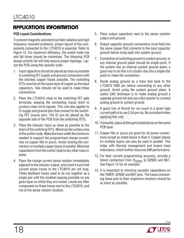
Programming Charge Current
Charge current is programmed using the following
equation:
R
SENSE
=
100mV
I
PROG
R
SENSE
is an external resistor connected between the
SENSE and BAT pins. A 1% resistor with a low temperature
Table 2. LTC4010 Charging Parameters
STATE
PC
FC
Open
GND
CHEM
PIN
BAT
CHEMISTRY TIMER
Both
NiCd
NiMH
t
MAX
/12
t
MAX
t
MAX
T
MIN
5掳C
5掳C
5掳C
T
MAX
45掳C
60掳C
60掳C
TOC
AR
GND
NiMH
Both
t
MAX
/3
5掳C
5掳C
PC: Precharge
FC: Fast Charge (Initial 鈥撯垎V Termination Hold Off of t
MAX
/12 Minutes May Apply)
TOC: Top-Off Charge (Only for NiMH
鈭員/鈭唗
FC Termination After Initial t
MAX
/12 Period)
AR: Automatic Recharge (Temperature Limits Apply to State Termination Only)
Table 3. LTC4010 Time Limit Programming Examples
TYPICAL FAST
CHARGE RATE
2C
1.5C
1C
0.75C
C/2
PRECHARGE LIMIT
(MINUTES)
3.8
5
7.5
10
15
FAST CHARGE
VOLTAGE STABILIZATION
(MINUTES)
3.8
5
7.5
10
15
FAST CHARGE LIMIT
(HOURS)
0.75
1
1.5
2
3
TOP-OFF
CHARGE
(MINUTES)
15
20
30
40
60
4010p
R
TIMER
24.9k
33.2k
49.9k
66.5k
100k
12
U
coefficient and sufficient power dissipation capability to
avoid self-heating effects is recommended.
Programming Maximum Charge Times
Connecting the appropriate resistor between the TIMER
pin and GND programs the maximum duration of various
charging states. To some degree, the value should reflect
how closely the programmed charge current matches the
1C rate of targeted battery packs. The maximum fast
charge period is determined by the following equation:
R
TIMER
=
t
MAX
(Hours)
(
鈩?/div>
)
30 鈥?10
鈥?
W
U U
Some typical timing values are detailed in Table 3. R
TIMER
should not be less than 15k. The actual time limits used by
the LTC4010 have a resolution of approximately
卤30
seconds in addition to the tolerances given the Electrical
Characteristics table. The maximum time period is ap-
proximately 4.3 hours.
I
CHRG
I
PROG
/5
I
PROG
I
PROG
TERMINATION CONDITION
Timer Expires
鈥?0mV per Cell or 2掳C/Minute
1.5掳C/Minute for First t
MAX
/12 Minutes if Initial
V
CELL
< 1.325V
鈥?0mV per Cell or 1掳C/Minute After t
MAX
/12 Minutes
or if Initial V
CELL
> 1.325V
60掳C
45掳C
I
PROG
/10
0
Timer Expires
V
CELL
< 1.325V


 1
1
 2
2
 3
3
 4
4
 5
5
 6
6
 7
7
 8
8
 9
9
 10
10
 11
11
 12
12
 13
13
 14
14
 15
15
 16
16
 17
17
 18
18
 19
19
 20
20
