鈳?/div>
2
where:
I
DD
= Average external INTV
DD
load current, if any
Q
TGATE
= Gate charge of external P-channel MOSFET
in coulombs
Q
BGATE
= Gate charge of external N-channel MOSFET
(if used) in coulombs
V
LED
= Maximum external LED forward voltage
R
LED
= External LED current-limiting resistor used in
the application
n = Number of LEDs driven by the LTC4010
Sample Applications
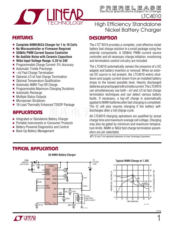
Figures 6 through 8 detail sample charger applications
of various complexities. Combined with the Typical
FROM
ADAPTER
5.5V TO 34V
3k
R
10碌F
49.9k
GND
0.1碌F
Figure 6. Minimum LTC4010 Application
4010p
14
U
Application on the first page of this data sheet, these
figures demonstrate some of the proper configurations
of the LTC4010. MOSFET body diodes are shown in these
figures strictly for reference only.
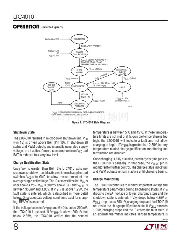
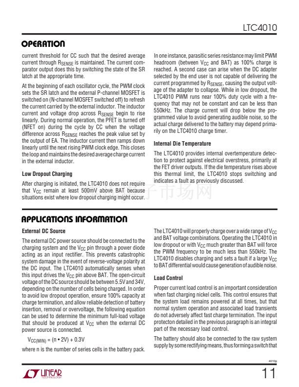
Figure 6 shows a minimum application, which might be
encountered in low cost NiCd fast charge applications. The
LTC4010 uses 鈥撯垎V to terminate the fast charge state, as
no external temperature information is available.
Nonsynchronous PWM switching is employed to reduce
external component cost. A single LED indicates charging
status.
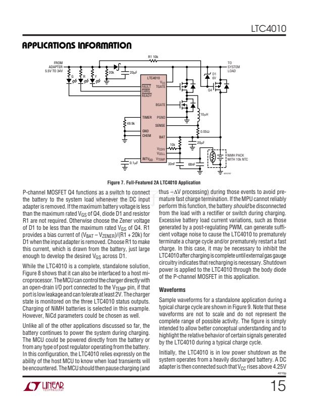
A full-featured 2A LTC4010 application is shown in Fig-
ure 7. The inherent voltage ratings of the V
CELL
, V
CDIV
,
SENSE and BAT pins allow charging of from one to sixteen
series nickel cells in this application, governed only by the
V
CC
overhead limits previously discussed. The application
includes all average cell voltage and battery temperature
sensing circuitry required for the LTC4010 to utilize its full
range of charge qualification, safety monitoring and fast
charge termination features. The V
TEMP
thermister net-
work allows the LTC4010 to accurately terminate fast
charge under a variety of applied charge rates. Use of a
synchronous PWM topology improves efficiency and re-
duces excess heat generation. A green LED indicates valid
DC input voltage and installed battery, while a red LED
indicates charging. Fault conditions are indicated by a
yellow LED. The grounded CHEM pin selects the NiMH
charge termination parameter set.
TO
SYSTEM
LOAD
LTC4010
FAULT
CHRG
READY
TIMER
V
CC
TGATE
BGATE
PGND
SENSE
0.1鈩?/div>
BAT
10k
V
CDIV
CHEM
V
CELL
INTV
DD
V
TEMP
56k
10碌F
NiCd
PACK
4010 F06
W
U U
10碌H
33nF


 1
1
 2
2
 3
3
 4
4
 5
5
 6
6
 7
7
 8
8
 9
9
 10
10
 11
11
 12
12
 13
13
 14
14
 15
15
 16
16
 17
17
 18
18
 19
19
 20
20
