LM4510
The output capacitor should be capable of handling the RMS
current.
The ESR and ESL of the output capacitor directly control the
output ripple. Use capacitors with low ESR and ESL at the
output for high efficiency and low ripple voltage. The output
capacitor also affects the soft-start time. See Soft-Start Func-
tion and Soft-Start Capacitor Selection. Table 3 shows sug-
gested input and output capacitors.
TABLE 3. Suggested C
IN
and C
OUT
Capacitors and Their Suppliers
Model
4.7 碌F for C
IN
C2012X5R0J475
GRM21BR60J475
JMK212BJ475
C2012X5R0J475K
10 碌F for C
OUT
TMK316BJ106KL
12103D106KAT2A
Ceramic, X5R
Ceramic, X5R
Taiyo-Yuden
AVX
25V
25V
1206 (3216)
1210 (3225)
Ceramic, X5R
Ceramic, X5R
Ceramic, X5R
Ceramic, X5R
TDK
muRata
Taiyo-Yuden
TDK
6.3V
6.3V
6.3V
6.3V
0805 (2012)
0805 (2012)
0805 (2012)
0603 (1608)
Type
Vendor
Voltage Rating
Case Size
Inch (mm)
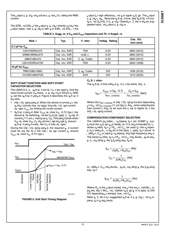
SOFT-START FUNCTION AND SOFT-START
CAPACITOR SELECTION
The LM4510 has a soft-start pin that can be used to limit the
input inrush current. Connect a capacitor from SS pin to GND
to set the soft-start period. Figure 6 describes the soft start
process.
鈥?Initial charging period: When the device is turned on, the
control circuitry linearly regulating initial charge current
charges V
OUT
by limiting the inrush current.
鈥?Soft-start period: After V
OUT
reaches V
IN
-0.7V (typ.), the
device starts switching and the C
S
is charged at a constant
current of 11
渭A,
ramping up to V
IN
. This period ends when
V
SS
reaches V
FB
. C
S
should be large enough to ensure
soft-start period ends after C
O
is fully charged.
During the initial charging period, the required load current
must be smaller than the initial charge current to ensure
V
OUT
reaches V
IN
-0.7V (typ.).
C
S
Selection
The soft-start time without load can be estimated as:
Where the I
INIT_CHARGE
is Initial Charging Current depending
on V
IN
and I
SS_CHARGE
(11 渭A
(typ.)). Also, when selecting the
fuse current rating, make sure the value is higher than the
initial charging current.
COMPENSATION COMPONENT SELECTION
The LM4510 provides a compensation pin COMP to cus-
tomize the voltage loop feedback. It is recommended that a
series combination of R
C
and C
C1
be used for the compen-
sation network, as shown in the typical application circuit. In
addition, C
C2
is used for compensating high frequency zeros.
The series combination of R
C
and C
C1
introduces a pole-zero
pair according to the following equations:
In addition, C
C2
introduces a pole according to the following
equation:
30031023
FIGURE 6. Soft Start Timing Diagram
Where R
O
is the output impedance of the error amplifier, ap-
proximately 1 M鈩? and amplifier voltage gain is typically 200
V/V depending on temperature and V
IN
.
Refer to Table 4 for suggested soft start capacitor and com-
pensation components.
13
www.national.com


 1
1
 2
2
 3
3
 4
4
 5
5
 6
6
 7
7
 8
8
 9
9
 10
10
 11
11
 12
12
 13
13
 14
14
 15
15
 16
16
 17
17
 18
18
