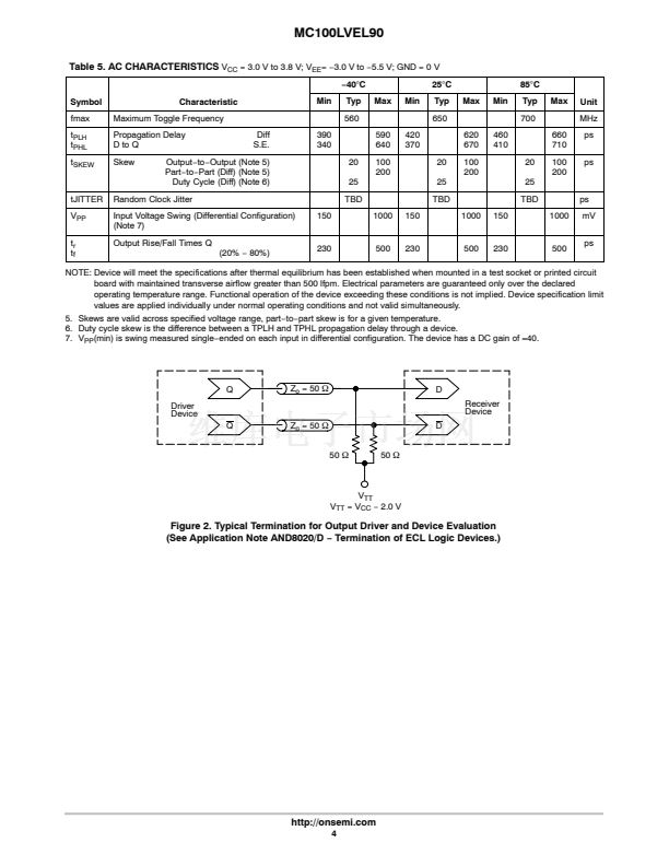
Table 5. AC CHARACTERISTICS
S.E.
鈭?/div>
80%)
ps
mV
ps
230
500
230
500
230
500
NOTE: Device will meet the specifications after thermal equilibrium has been established when mounted in a test socket or printed circuit
board with maintained transverse airflow greater than 500 lfpm. Electrical parameters are guaranteed only over the declared
operating temperature range. Functional operation of the device exceeding these conditions is not implied. Device specification limit
values are applied individually under normal operating conditions and not valid simultaneously.
5. Skews are valid across specified voltage range, part鈭抰o鈭抪art skew is for a given temperature.
6. Duty cycle skew is the difference between a TPLH and TPHL propagation delay through a device.
7. V
PP
(min) is swing measured single鈭抏nded on each input in differential configuration. The device has a DC gain of
鈮?0.
Q
Driver
Device
Q
Z
o
= 50
W
D
Receiver
Device
Z
o
= 50
W
50
W
50
W
D
V
TT
V
TT
= V
CC
鈭?/div>
2.0 V
Figure 2. Typical Termination for Output Driver and Device Evaluation
(See Application Note AND8020/D
鈭?/div>
Termination of ECL Logic Devices.)
http://onsemi.com
4


 1
1
 2
2
 3
3
 4
4
 5
5
 6
6
